Continue to Site

Welcome to our site!

Electro Tech is an online community (with over 170,000 members) who enjoy talking about and building electronic circuits, projects and gadgets. To participate you need to register. Registration is free. Click here to register now.

  • Welcome to our site! Electro Tech is an online community (with over 170,000 members) who enjoy talking about and building electronic circuits, projects and gadgets. To participate you need to register. Registration is free. Click here to register now.

JDY-10 Bluetooth BLE Uart Transceiver Module

Status
Not open for further replies.

ACharnley

Member
I couldn't find anything on Google so to save others the time required to find out anything decent about this small module I'm creating this thread which will be indexed by Google.

STATUS: THIS MODULE IS WORKING (with issues)

The JDY-10 uses the TLSR8266 chip which has an impressive specification and low power requirements. It's currently the cheapest BLE module on Aliexpress. As with all these various modules, key lies in the quality of the firmware.

Eventually I found a Chinese datasheet which I've attached. Google will do a pretty good translate of it. You can use the URL to find a store which reveals the company name and then google that for the company URL. The price/unit is $0.99 direct.

The chip runs at a default baud of 115,200. There is an AT+BAUD command to change it. I wish they'd used 9,600 as 115.2k isn't available with PIC MCU RC oscillator's running at 8MHz.

You can change the BLE exposed name but the last character is always missed off, so add a random character.

On boot it prints "Star...".

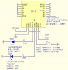
To force command mode (in case of active connection) the pin B0 (according to the datasheet) must be grounded.

There is a sleep mode (two states) but they doesn't work. It appears to be part implemented in that the commands work (and pin to "wake" it up) however in "sleep" mode the Bluetooth is still active and accepting a connection. UART still works and the LED outputs continue output. Since the device consumes ~10mA I worked around this by driving the device directly from a MCU pin.

I had the key parts related to pin B0 translated and I've included them below.

µÍµçÆœ AT ģʜ,ĬÈÏžßµçÆœ
AT mode of Low level is default high level

ŽËÒýœÅÔÚÒÑÁ¬œÓÇé¿öϲ»ÐèÒª·¢ AT ÖžÁîµÄ»°, ¿ÉÒÔ²»
ÓùÜ,Ðü¿ÕŸÍÐÐ
The pins can be ignored and suspended if there is no required to send the AT command under the connected condition.

µ±ÒªÇóÔÚÁ¬œÓµÄ׎̬·¢ AT ÖžÁîʱ,ŸÍœ« B0 ÒýœÅ±£³Ö
µÍµçÆœ,ŸÍœøÈë AT ģʜ,Óû§ŽËʱŸÍ¿ÉÒÔ·¢ËÍ AT Öž
Áî,Òª·¢ÍžŽ«ÊýŸÝʱŸÍœ« B0 ±£³ÖžßµçÆœ,ŸÍÁ¢ŒŽœøÈë
ÍžŽ«Ä£Êœ
When it require sending the AT command in the state of the connection,
then just keep low level for the B0 pin, it enters the AT mode,and the users can send AT command at this time.
When it require to send passthrough data,then keep the B0 maintain a high level,
then it will immediately into passthrough mode.


ÊÇ·ñÔÚÎŽÁ¬œÓµÄÇé¿öÏ·¢ AT ÖžÁîÐèÒªœ« B0 ±£³ÖµÍµç
Ɯ ?
Does it need to keep the BO low level if we want to send the AT command at the state of unconnected?


Žð:²»ÐèÒª,Ä£¿éÔÚÎŽÁ¬œÓµÄ׎̬ÏŸÍÊÇ AT ģʜ,ÓÃ
»§²»ÐèÔÚÒÑÁ¬œÓÇé¿öÏ·¢ËÍ AT ÖžÁî ,B0 ÒýœÅ¿ÉÒÔÐü
¿Õ

Answer: no, the module is AT mode in an unconnected state.
B0 pins can be suspended if the user does not need to send the AT instruction under the connected condition.

ATÖžÁî¿ØÖÆÒýœÅ
Á¬œÓ׎̬Ï£ºµÍµçÆœATģʜ
ÍžŽ«Ê±£ºÐèÒªÀžß
ŽËÒýœÅÈçÓò»ÉÏ£¬¿ÉÐü¿Õ

AT command control the pins
Under connected condition:low level AT mode
Passthough condition:need draw high
The pins can be suspended if it do not be used.
 

Attachments

  • ic.png
    ic.png
    58.1 KB · Views: 792
  • bluetooth40_en.pdf
    851 KB · Views: 978
Last edited:
Hi, thanks for the info. I bought a module like this. It reports its Bluetooth name as JDY-10-V2.4 on my Android device. I tried to pair with it but it will not pair. I read that giving it an AT command of AT+TYPE3, or something like that it was, and rebooting it will make it able to pair with Android. I am having trouble getting a terminal session running with it. Can you confirm the procedure to get a terminal session running with it ? I have a USB to Serial adapter connected to the RX and TX pins of the module. I tried the screen terminal under linux, and the Arduino serial terminals to communicate with it but get no response. Could you confirm the baud rate line endings, caps no caps etc... and anything I might be missing ?
 
I made mine work and I wish I'd wrote it down as I'll have to repeat it at some stage. The pdf I attached previously was wrong so I've attached the correct one.

Make sure the red +V from your serial adapter is not connected, usually they are 5v and will fry the chip.

As I recall (and don't quote me) the B0 pin must be pulled low (or high?) to enter AT mode otherwise none of the commands will work. AT+TYPE is only for the JDY-08 which supports master. The JDY-10 is slave only.

First you have to understand how BLE works, it doesn't pair automatically like normal bluetooth but is done by an App. This is because BLE doesn't have any protocols so is OS useless.

Instead there are ID's and best practices of which corresponds to services;

https://www.bluetooth.com/specifications/gatt/services

A service has characteristics and these can be shared between services.

https://www.bluetooth.com/specifications/gatt/characteristics

Try using Linux and hcitool/gattool to connect that way. There is a characteristic which references the data connection and it's half duplex which is where the fun of writing your own protocol begins. This is where my knowledge is fuzzy but I recall using gattool to read the ID. There's some sort of read/push feature which automatically prints incoming data to the terminal, this is what you want.

https://www.jaredwolff.com/blog/get-started-with-bluetooth-low-energy/

I also used cutecom for the modem terminal. Use 115200 and find your adapter under /dev/ttyUSBx. You need to configure it to send CR+LF characters upon <enter>. This is much better than JDY-08's stupid delay=send. Sometimes with the USB adapters can't tell which is RX or TX. RX has to go to TX on the BLE module.

Using these two I managed to get data going between the two. I think it can only send one character/byte at a time but I honestly can't remember and might be making that up. At the point at which I knew I could get data going between them I committed to using it in my PCB. That's how much hassle I had with other units and how desperate I'd become.

BTW look at the B0 pin. By default the unit is in transparent mode (or not?) and it works to disable all the AT commands. The only one I needed was AT+NAME and I got it working. Note it has a stupid bug, the last character is omitted so to change the name to "Dog" you need to do AT+NAME=Dogx (maybe the = is not required I can't remember). I've connected this pin to my MCU so I'm pretty sure it's critical.

I'll be knee deep in JDY-10 in a few weeks time as my prototypes are back from the fab then and the programming fun begins.
 

Attachments

  • JDY-10蓝牙4.0模块V2.4.pdf
    300.4 KB · Views: 1,026
  • IMG_0994.JPG
    IMG_0994.JPG
    273.7 KB · Views: 390
Last edited:
Thanks for your helpful response.

Looks like my initial setup was actually correct. Problem was this module does not respond to AT with OK. It just does not respond... It will respond with OK to other things like setting the name which is done with AT+NAME YourName. Or give version info AT+VER etc. This is the first time I work with any modem or any at command mode device which does not respond to AT or AT+ with OK so I thought my setup was wrong. FIY I can confirm that this module will accept ( in the unconnected state ) AT commands regardless of the state of B0. Looks like, according to the datasheet, the state of B0 is only relevant when in the connected state. Low to accept AT commands. Which would explain why you have it brought in your design...

BTW My module did not cut off the last letter of the name when setting it. It just works as expected. V2.4.
 
Probably there's two V2.4 versions, it's Chinese after all. :)

Most AT commands don't work, it's much simpler than JDY-08 due to lack of master mode. It sounds like once you make it connect you should be able to get some data flow going.
 
This is baffling me. I use the Arduino IDE serial monitor to send this module AT commands without a problem. When trying to use cutecom it does not seem to work. I have the cutecom settings on the correct device name ( it will connect ). Baud is correct at 115200. 8N1 Parity none. Handshake off. I think I tried it on "on" also without success. I set it to CR, LF line end. Char delay 1ms. It should work no ? Can you confirm the cutecom settings ?
 
Char delay 0ms. Everything else is correct. I have Hex Output box ticked but shouldn't matter.

If that doesn't work try swapping the RX/TX wire. Also ensure the 5v red from your reader is not connected, the 5v will crash it.
 
Ok now it works at 0ms delay. Ty. I noticed an "interesting" thing about my module. I did an AT+DEFAULT, the command to reset the whole thing. And now the name became
JDY-10-V2.1 which previously was JDY-10-V2.4 . AT+VER reports +JDY-10-V2.4 . So now I have a hybrid. ( Kidding ) Its so all Chinese.
 
I managed to get full two way serial communications going with this device in transparent mode. Communications between an Android app and my linux laptop. Great so I can use it. However, can you perhaps shed some light on something ? I would like to be able to set any of the GPIO pins from my Android app. I read in the datasheet:
"pin 2 E5 IO5 Output IO pin can be controlled by APP level. "

I just want to turn on and off an LED.
There is no indication in the datasheet as to how to do this. The datasheet talks about an Android test app called JDY-LED but this program is nowhere to be found.

I guess first thing would be to put it in the LED mode the datasheet is talking about: "AT+CLSS A0: transparent mode
B1: LED light mode"

Then I'm not sure. I guess one should then write data to a characteristic after connecting to a service. But what data ? The actual real HM1x modules have AT instructions to control PIO pins. This module has no such AT instructions mentioned in the datasheet. Besides, this module will not accept AT instructions directly from the Bluetooth interface radio input it wants the AT commands always via the onboard rx and tx pins. So an AT command is not going to be what I want. I'd love to be able to use just this tiny thing to control things with a minimum of hardware.
 
JDY-10-V2.4手册/JDY-BLE-SDK-V1.4/其它源码/IO_CTRL/ ?

I'm not using any IO's and haven't played with setting them sorry.
 
Was that a link or part of a link or something you left ? I did a search for those terms, Google yields nothing appropriate. Baidu.com gave me a trace to JDY-BLE-SDK-V1.3 which I finally downloaded. But is there a V1.4 ? Where ?
 
Let me know if it helped. I tied one of the led outputs (STAT / ADV_LED) into my MCU and need to release one for another task. Have you played with them? Basically I'll need to know if a device is connected.

I need to automate a check of the device name, change if necessary and the connected client can't interrupt during this time. Probably B0 disables transparent mode but I could be wrong.
 
I have not played with the GPIO pins yet. I have only used this device in transparent mode which is the default. B0 can disable/enable AT command mode for when the device's radio is connected. I am not aware of any other function or effect. The device will always accept AT commands on its RX and TX regardless of the state of B0 if the radio is not connected. But if it is connected then B0 must be used to enable or disable AT command mode. Not sure how you would go about checking if a device is connected. One way that comes to mind is to do a comms test.
 
That's how I understand it. A comms test assumes the connected device understands the command/protocol. I'm thinking one of the LED outputs tied into the MCU will do it.

Not sure which one though!
 
That's not BLE Toni.

I'm using the JDY-10 in my application now and it's working ok. I've updated the top post to include some pointers to issues (sleep especially).
 
Hey, i'm trying to use that JDY-10 boards .. but ifound an issue ..
I'm using service "ffe0" and charatreristics "ffe1" to transfer data. ( i assume that 20 bytes as max is enought for me )
Now i connected pcb via serial chip to terminal on PC that i can set name and read values
I have "connected" / "disco" on BLE service connection / disconnection .... until now it is fine.

Second part i'm using - currently ESP32 BLE client / or BLE terminal whitch uses mentioned characteristics.
So when i send 0x32 byte I'm having reply from JDY-10 it's name. every time .. even if 0x32 byte is in string value. anyone got such issue ?
That should be transparent as i belive.

My bad, i had auto reply function in my terminal, that made me confused.

I must check only what is said in provided datasheet about accepting AT commands via FFe2 uuid ...
 
Last edited:
Has anybody a PC software which is able to connect to the JDY-10 (with BT)?
I am able to send data from IOS and Android apps, but I cannot find any software for Windows 10.
C# source would be the best to integrate my testcode,
I found some windows example(https://github.com/Microsoft/Windows-universal-samples/)
It is able to connect to my MiBand2 but not able to connect to JDY-10
 
Status
Not open for further replies.

Latest threads

New Articles From Microcontroller Tips

Back
Top