Electro Tech is an online community (with over 170,000 members) who enjoy talking about and building electronic circuits, projects and gadgets. To participate you need to register. Registration is free. Click here to register now.
Welcome to our site! Electro Tech is an online community (with over 170,000 members) who enjoy talking about and building electronic circuits, projects and gadgets. To participate you need to register. Registration is free. Click here to register now.
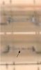
I have a friend who has a crossover that's not working.. So here is a picture of it i checked the bulbs, resistor and the coils which all tested good..
I tested the coils and no broken wire or anything... I'm lost.
Those "bulbs" look like some kind of mickey mouse surge protection or fuses (?) so they should be irrelevant (unles they are shorting across the lines or blown open). check continuity
Check the inductors for continuity, but the caps are always most likely to fail. Beware of polarity, they might be non-polar electrolytics.
The yellow cap between the inductors is some kind of poly film type. The white part next to it is a wirewound power resistor.
Ok I'm home now again so yeah I just tested as i told another person I've already checked everything so far for continuity the only thing now really is to check the caps.. The yellow cap I tried to look up info but I'm not really finding anything on it.. However it seems to be fine.. I have two other little white things which i think are resistors I'd have to get a macro shot of it since they are small.. going to remove one of the caps now to check.
But for sure when I check for continuity on the woofer output it's open.
A tungsten bulb is essentially a current dependent resistor. I've had an amp that had a dual bulb as an emitter resistor to a transformer coupled amplifier.
Capacitors couldn't really stop the woofer working, unless one was S/C across it - which is so unlikely as to not be worth checking (but you already have anyway).
There's nothing in there to go wrong, and certainly nothing worth asking about on a forum - the bass signal probably goes though an inductor direct to the speaker coil, then back out on the other terminal. It's that simple, there 'may' be a fuse perhaps in series as well, but it's unlikely on the woofer, more normal on the tweeter.
It's a simple low pass filter with a single inductor and cap on the LF, the rest of the circuit is for the HF. Check each line in turn for continuity from input to output. Work your way back towards the input with one lead of the meter. If need be, test the actual PCB traces for a possible crack by scraping a smidge of resist off etc. It's not uncommon to crack the board around an inductor mount/ tie wrap etc when the cabinet is banged around. Bose and H&H/ Fane setups etc sometimes use polyfuses for protection as well as lamps, but I don't see any on your board, just the lamps. Lansing generally mark their protection lamps with a dot of coloured paint, so if they have failed, replace both at the same time with the correct ones. They are available from JBL, but you need to tell em what colour the dot is.
I still can't believe I'm the only one who can see the bottom "fuse" is blown in the center. The input line labeled "+W" looks like it runs directly to the end of the fuse.
I still can't believe I'm the only one who can see the bottom "fuse" is blown in the center. The input line labeled "+W" looks like it runs directly to the end of the fuse.
The pictures too small to tell - you might be simply imagining it.
But in any case, simple ohm meter tests (as you would automatically do before posting such a trivial question on a forum) would immediately find such a fault (faster than typing the question here).
not sure why you are "upset" like I said I checked that the only thing I found interesting is the ceramic resistor seems to be off it's 10W 16 ohm however I only get 1.1 ohm reading from it.. Now I really can't find a direct replacement for the ohm.
I checked the coil from that to the +W it's open, From the 2 red inputs to the +W I have continuity between those two wires to +W
However not from the large coil to the +W on the side of the white resistor where the black tape goes around however I do have it if I test both ends of the coil.
This site uses cookies to help personalise content, tailor your experience and to keep you logged in if you register.
By continuing to use this site, you are consenting to our use of cookies.