Continue to Site

Welcome to our site!

Electro Tech is an online community (with over 170,000 members) who enjoy talking about and building electronic circuits, projects and gadgets. To participate you need to register. Registration is free. Click here to register now.

  • Welcome to our site! Electro Tech is an online community (with over 170,000 members) who enjoy talking about and building electronic circuits, projects and gadgets. To participate you need to register. Registration is free. Click here to register now.

Isolating microcontroller from motor

Status
Not open for further replies.

phoenox

New Member
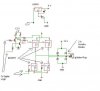
I am trying to use a PIC to control a 12V DC electric motor.

I am having problems with the noise from the motor causing MCU instability.'

The circuit is powered by a 12 V battery with a LM341 Voltage regulator for 5 V power. I already have two seperate ground planes for with a schotky diode seperating them.

Does anybody know a better way of isolating the digital power?
 
Post a schematic, this could be anything.
 
Also you want backspike diodes on the motor drivers. A schemtic of the drive section would be really helpful.
 
Here is the schematic.

There are backspike diodes but no capacitor.

What size of capacitor will I want to use?
The motor specs say 24 - 36 V, 2.75 A.

Whan I run it at 12 V it draws about 1 A steady state.

Thanks for the help.
 

Attachments

  • power sch.jpg
    power sch.jpg
    21.2 KB · Views: 800
Just try a 0.1uF ceramic capacitor soldered DIRECTLY across the motor terminals (not somewhere else down the wire). Size doesn't matter so much (meaning it's a black art or you don't often have enough data to make the perfect choice)...just make sure it's a good high frequency capacitor that is NON-POLARIZED (like a ceramic cap) that is rated for at least 2x the operating voltage (preferably 4).

But more importantly, it looks like you have no power supply smoothing at all to absorb voltage spikes and dips caused by the battery having a lot of inductance and taking time to react to changes caused by the motor. Place a large capacitor in parallel with your battery. For your motor I would say start with at least 1000uF electrolytic capacitor with a voltage rating at least double the battery voltage, tied as close as possible to the electronics minimizing wire length between capacitor and electronics (ie. not right next to the battery).

Input capacitors on the regulator also would not hurt (1uF or so) and something similar for the output as well. The smaller capacitors like 0.1uF should be right next to your IC's power pins, not the output of the regulator...too much inductance (ie. wire or PCB trace) between capacitor and power pin defeats their purpose. THe smaller the capacitor (a.k.a. the higher frequency the capacitor is supposed to handle) the more this holds true.

As for your separated power planes...beware...improper routing will force the return current for signals in your system to have to take a larger looped path due to the separate ground planes, causing increased EMI/RFI emission. If you don't know the caveats of split ground planes, don't use them. They can cause more problems than they solve. Read this article:
Grounding of Mixes Signal Systems
https://www.electro-tech-online.com/custompdfs/2009/01/dash_jan08_tech.pdf
 
Last edited:
He needs a 12V filter cap, too, a good sized one. A small one near the input of that LM341 is also a smart idea, and I would remove that diode from the regulator's ground pin.

Where do you have "two seperate ground planes for with a schotky diode seperating them" - ?
 
The regulator ground pin is attached to the digital ground plane. All the digital circuitry is grounded to this ground plane. The diode in the schematic connects this plane to the analog ground plane which is attached to the battery negative post. I thought this would keep some of the motor noise from getting to the digital circiutry. Is this incorrect?

I have .1uF capacitors near the power pins of digital circuits. I have added one across the motor, also two 4.7uF capacitors in parallel at the regulator input.

There is a 47uF capacitor at the output of the regulator. This is the capacitor that was shown but not labeled in the schematic. I suppose that this is too big and I should replace it with a smaller capacitor? How do you know what size of capacitor to use?

I do not have any 1000 uF capacitors around. I will have to order some before I can add one to the circuit.
 
The size of decoupling capacitors is not too critical. Larger currents requires larger capacitors (which will work decently at low frequencies but not high frequencies due to parasitics) and higher frequencies is smaller capacitors (that don't work well for larger currents because they have less capacitance).

If you get high currents with high frequencies, then things get tricky.
 
Last edited:
The diode in the schematic connects this plane to the analog ground plane which is attached to the battery negative post. I thought this would keep some of the motor noise from getting to the digital circiutry. Is this incorrect?
Lose the diode on the LM341's ground pin. It will cause temperature instability and adds apx 0.7V to the output voltage. Add a 0.1uF ceramic cap on the output and a 0.33uF ceramic on the input of the LM341. Place these as close as possible to the LM341.
Don't run the high current path from the H-bridge through the ground circuit of the rest of the circuit on it's way to the battery. Instead have separate ground return paths for the high current and MCU circuitry. Do the same with the positive supply.
 
Don't run the high current path from the H-bridge through the ground circuit of the rest of the circuit on it's way to the battery. Instead have separate ground return paths for the high current and MCU circuitry. Do the same with the positive supply.

I'd be careful about that. That is making a ground loop and might cause more problems than it solves. It might just be easier to make a single large low impedance ground plane.
 
Last edited:
Can you describe this "MCU instability" to us, phoenox? Bad reads on an A/D convertor, processor reset, unusual port operations, what?
 

Attachments

  • GoodBad.PNG
    GoodBad.PNG
    22.3 KB · Views: 1,489
Last edited:
Have a look at the Silicon Chip (Silicon Chip Electronics Magazine for Hobby Electronics, Computing, Kits and Projects.) magazine, March 2008 page 33.

They have a 2200 uF low ESR capacitor across the battery, a 100 Volt 220 nF MKT polyester cap across the motor (diode also), a 100 Volt 100 nF MKT polyestercap across the switching MOSFETs (& a Zener).

They also attenuate and filter the EMF before it goes to the PIC analogue input.

Also, the point that someone made about the gnd connections is vital.

The heavy currents cause voltage drops across the tracks so you must ensure that these do not cause noise in the PIC gnd line.

Of course, they also have a 470 uF in parallel with a 100 nF monolithic cap across the PIC Vdd/Vss pins.

Where did you obtain info on the PIC programme algorithm?

I have been thinking about this issue and would like to know how to determine the PWM Duty Cycle when the motor load changes.

For example, say it is controlling an electric drill.

When you start the drill and adjust the speed to say 1000 RPM and then start drilling. The speed will decrease and so the PIC has to adjust the DC to compensate.

Obviously, the increase in the DC is a function of the decrease in the EMF. But how is it calculated?
 
Last edited:
In addition to kchriste's drawing:
-"voltage drop" is created by the high H-bridge current running through the wire resistance. THere's voltage drop everywhere else too, but the current from the other circuits is nothing compared to the H-bridge current.

-The thing to avoid is having a "looped path of wire" where the voltage along the entire loop is supposed to be ground. In a perfect world this works, in real life this makes an antenna to receive noise and radiate noise.

For example, this would occur if you:
1. gave the H-bridge ground a separate wire straight to the battery ground
2. gave the MCU/logic ground a separate wire straight to battery ground
3. had a third wire to directly connected the ground between electronics and H-bridge

Take away one of these wires and it becomes a "star-connected ground" which is good, and not a problem. (assuming that is all there is for ground wires).

THere are tradeoffs in picking which wire not to have. Wires 1 and 2 give each section of the circuit it's own dedicated wire to ground, but signals sent between the two will have to take the longer loop since they must return using the other sections' ground wire (ie. signals sent from the MCU to H-bridge would need to travel through the H-bridge ground wire to return back to the MCU/logic section). THere is also how the groudn voltages might be different since higher currents in the H-bridge ground wire produces a larger voltage drop than the much lower currents in the MCU/logic wire.

Removing either wire 1 or wire 2 allows signals sent between the sections to return very quickly to the section since they just take the direct ground between the two sections making a smaller loop. THe catch is that the ground has effectively been daisy chained (the section farthest from the battery is using the same ground as the section closest to the battery. THis is good if the circuit with the highest current (h-bridge is closest to the battery since it will produce a larger voltage drop along the wire, and then MCU/logic with much lower current draw will have a very similar ground voltage- not so good the other way around since the ground voltage between the two sections will be much different).
 
Last edited:
ljcox, in order to implement simple velocity control use proportional control:

while(1)
{
power = power + k (desired velocity - velocity)
}

make sure the proportional constant (k) is not too high or you will end up with wild oscilations.

for beter response you can also add a derivitive(rate of change) term to the equation.

while(1)
{
power = power + k (desired velocity - velocity) - kp(d/dt(velocity))
}

Thanks again to everyone for all the responses. This forum is great!

Thanks for the tips.
 
There would be loading on the microcontroller if the microcontroller drives the mosfets directly. So the microcontroller needs to be electrically isolated from the driver circuit/mosfets.

Use an Opto coupler between the microcontroller and the mosfets' inputs.
This setting will not load the microcontroller.
 
Status
Not open for further replies.

New Articles From Microcontroller Tips

Back
Top