Continue to Site

Welcome to our site!

Electro Tech is an online community (with over 170,000 members) who enjoy talking about and building electronic circuits, projects and gadgets. To participate you need to register. Registration is free. Click here to register now.

  • Welcome to our site! Electro Tech is an online community (with over 170,000 members) who enjoy talking about and building electronic circuits, projects and gadgets. To participate you need to register. Registration is free. Click here to register now.

Isolated Voltage Sense

Status
Not open for further replies.

drkidd22

Member
Hello,

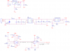
I'm trying to design a circuit where I can sense the voltage (24VDC) from an isolated converter. I'm using the AMC1200-Q1 from TI as the sensor. It's supposed to be a current sense, but I'm not interested in sensing the current drawn, just voltage. Reason to check this voltage is because it's (enabled in another part not shown) to power a different section. OPA2234 is just to amplify the voltage. The +24VDC_CHK is going to an analog input on a pic micro. Not sure what you guys use out there for this type of application, but I want to see what others have done and if there is a simpler way. I though of adding a high value resistor from B_GND to A_GND, but wouldn't that violate isolation?
 

Attachments

  • Capture.PNG
    Capture.PNG
    31.7 KB · Views: 229
hi,
I would use one of these linear opto isolators.

E
 

Attachments

  • HCNR200.pdf
    236.8 KB · Views: 151
I did this project a year ago.
I don't have time now....... Maybe tonight.
1) You have one of the outputs shorted to ground (isolator). NO. Let it be NC.
 
Last edited:
hi,
The LOC datasheet shows that the current for the opto LED is 2 to 10mA, so assume 8mA.
The LED typical forward voltage drop is 1.2V.
The OPA driving the opto resistor/LED is powered by 5V, so assume 4.5V out max.
So the LED resistor is [4.5v - 1.2v]/0.008 = 412 Ohms, so I would use a 430R resistor.
OK,?
E
BTW: there is a LED resistor calculator in the Tools section of ETO.
 

Attachments

  • A01.gif
    A01.gif
    16.2 KB · Views: 197
Last edited:
1)"Wide Supply Range:VS= ±4.5 to ±24 V" You only have +5V and 0V. Choose a low voltage part not a high voltage part.
2) "Common-mode input range" Supplys-3 volts. In this case; 5-3=2 and 0=+3=3 so there is no input voltage that will make the parts work because the supply is too low. You need a input range that includes ground and maybe close to +5V. So look for a RR input (rail to rail).
3) This part will output the 10mA you want but it will take most of the 5V supply to do that. (it will not deliver 10mA with an output voltage of 4.5V as suggested in post #5) You will need to have a 0 ohm resistor to get this output with this opamp.
4) This part does not need to be so fast.
Sorry for the bad news.
capture-png.100413
 
hi,
The LOC datasheet shows that the current for the opto LED is 2 to 10mA, so assume 8mA.
The LED typical forward voltage drop is 1.2V.
The OPA driving the opto resistor/LED is powered by 5V, so assume 4.5V out max.
So the LED resistor is [4.5v - 1.2v]/0.008 = 412 Ohms, so I would use a 430R resistor.
OK,?
E
BTW: there is a LED resistor calculator in the Tools section of ETO.

If you look at the Vishay IL300, page 8 data sheet (https://www.vishay.com/docs/83622/il300.pdf) they say that the output of the high side op amp is target for 50% of VCC so they select a 100 Ohm resistor. How is this output determined or did they just pick an assumed minimum V output?
 
they say that the output of the high side op amp is target for 50% of VCC so they select a 100 Ohm resistor. How is this output determined or did they just pick an assumed minimum V output?
Most OP-amps have a graph of output voltage and current (at some supply voltage).
Some op amps can not pull to the supply at all at any current.
Example:
output @ supply = 0 current,
output @ supply-1V = 1mA,
output @ supply-2V = 8mA,
output @ supply-3V = 16mA,
This is very different for every part. The OPA2604 has strong outputs but is a high voltage part not given to working well at even 9V supply.
See post #7.
 
This is for a ua741. Don't use this old part either.
With a +15V supply and -15V supply (so 30V supply).
If the load was a 10k resistor then the maximum output will swing +/-14V. (supplys-1V). Probably with no load you can not get with in 1V of the supply.
With a 1k load the outputs can not reach supply-3V. (+/-12V)
With a 100 ohm load you really can not get any output.
upload_2016-7-13_6-32-42.png
At
 
1)"Wide Supply Range:VS= ±4.5 to ±24 V" You only have +5V and 0V. Choose a low voltage part not a high voltage part.
2) "Common-mode input range" Supplys-3 volts. In this case; 5-3=2 and 0=+3=3 so there is no input voltage that will make the parts work because the supply is too low. You need a input range that includes ground and maybe close to +5V. So look for a RR input (rail to rail).
3) This part will output the 10mA you want but it will take most of the 5V supply to do that. (it will not deliver 10mA with an output voltage of 4.5V as suggested in post #5) You will need to have a 0 ohm resistor to get this output with this opamp.
4) This part does not need to be so fast.
Sorry for the bad news.
capture-png.100413

1. I'm still within the limits right? At +5 Supply and gnd (0), why chose a low voltage if I still meet the spec?
2. Where is the 3V coming from in your 5-3 = 2? The data sheet says the common mode range is +-13V
3. What about an OPA2132 or if I tie the supply to the +24VDC?
 
1. I'm still within the limits right? At +5 Supply and gnd (0), why chose a low voltage if I still meet the spec?
2. Where is the 3V coming from in your 5-3 = 2? The data sheet says the common mode range is +-13V
3. What about an OPA2132 or if I tie the supply to the +24VDC?
1. On the first page of the data sheet the minimum supply is +/- 4.5V or 9V.
2. Yes +-13V with a +/-15V supply. (+/-13 typical and +/-12 minimum) But you have a +5/-0V supply. The data sheet said; stay (2V typ. 3V min) off the rails. Even at typ. the inputs can only work from 2V to 3V. That is not a guarantee. To make every part work you need to be 3V above the (-) supply and 3V below the (+) supply.
3. If you run from a 24V supply there will be heat in the op-amp when you are driving 8mA. Also you still have the problem if the inputs can't be run near ground.
 
Now you have a low voltage part. Built for 2.5 to 5V supply. 5.5 max.
R-R inputs; now you can run at ground and up to 5V on the inputs. (actually can run slightly beyond the supply voltage)
R-R out is OK. At room temperature; it can deliver 10mA at 0.5V from the supplies.
This part is not as fast. It probably will not oscillate if handled wrong.
This looks like a good part for the job.
 
I'm jumping late on the game, but....
the late Bob Pease, the famous analog guru from National Semiconductor, once showed a high linearity analog isolator utilizing a pair of LM331s.
One of them as a V/F converter, the other as a F/V converter.
 
What is your supply voltage and what voltage do you want at the PIC input for the measured 24V?
 
What is your supply voltage and what voltage do you want at the PIC input for the measured 24V?

The pic A/D has a 3V ref, so I'm trying to get the 24V down to 1.5V, 50%. That's what the divider formed by R459 and RR460 is doing.
But because it's isolated I'm using the LOC112 or might even use the IL300.
 
I used the AMC1200 and have played with the IL300.
Any time you add parts there is more error. How accurate do you need to be?
 
I used the AMC1200 and have played with the IL300.
Any time you add parts there is more error. How accurate do you need to be?

It does not to be very accurate, I'm shotting for 3-5%.

Back to the OPA2604 and common mode-input voltage range in general.
I'm still confused about the common mode-input voltage range. According to the sheet I need to stay 3V min off the rails. I'm not "using" the lower rail, its tied to ground, therefore I cannot be 3V above it (is this bad? already a violation and why it wouldn't work?).
I'm supplying 1.5V (24V divided) to the non-inverting input so 5-1.5 = 3.5, I'm 3.5V off the top rail, so I meet this requirement. I though this could have worked with no problem, but I'm having issues understanding it. Can you explain a little more please?
 
There are many different ways to build a op-amp input but here is one.
Because you have ground as the most negative voltage I built it that way.
T5 is a constant current source. It really wants 1V or more across it.
The inputs are Darlington. The Base to Emitter voltage is 1.2V. So the inputs will not work well (at all) until they are 2.2V above ground.
So this type of amp needs the inputs to stay away from ground. Look at input to ground connection. There are three B-E junctions plus the voltage on R1.
upload_2016-7-14_6-59-12.png
 
Status
Not open for further replies.

Latest threads

New Articles From Microcontroller Tips

Back
Top