Continue to Site

Welcome to our site!

Electro Tech is an online community (with over 170,000 members) who enjoy talking about and building electronic circuits, projects and gadgets. To participate you need to register. Registration is free. Click here to register now.

  • Welcome to our site! Electro Tech is an online community (with over 170,000 members) who enjoy talking about and building electronic circuits, projects and gadgets. To participate you need to register. Registration is free. Click here to register now.

Isolate

Status
Not open for further replies.

happyfpga

New Member
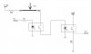
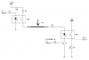
I need to deisgn a circuit to verify the connectivity (no open, no short) of eight data lines. I plan to use two I/O ports on one MCU, one port send data and another port receive data to do comparing. The same circuit will be used in another applicaiton case, 2-3 data lines will be fed with 35 Vdc from another device. To avoid damaging, the i/o ports of MCU need to be isolated. Is there any suggestion for the device for the isolation? If I want to use optocouplers (I/O -> optocouple -> optocouple -> I/O), how can I connect two coptocouplers together? Any suggestions are welcome.
 
If I want to use optocouplers (I/O -> optocouple -> optocouple -> I/O), how can I connect two coptocouplers together?
You can't. But you could do this:
I/O -> LineDriverIC -----> optocouple -> I/O
Post a schematic of the circuit (another applicaiton case) if you want more details.
 
kchriste, thanks for the reply. I am attaching the sch. If you think the circuit doesn't work, could you explain more?

there are two working modes required.

1. For working mode 1, I need to test the connection of 8 lines (thick line between two terminals) to make sure there is no open on each line and no short between each other. So I use two I/O ports of MCU, one for TX transmiting HEX data to another RX port for comparing.

2. With mode 2, these 8 lines will be used to transmit 35VDC and some logic signals.
 

Attachments

  • opto2.JPG
    opto2.JPG
    17.2 KB · Views: 154
The problem with your circuit is that you'll always be injecting 12V onto the lines via R2 which will interfere with mode 2. It also won't check for shorts between the lines. Here is a modified version of your diagram which should work. You could replace OPT1 with a PNP & NPN pair or a line driver IC (with diodes) to reduce cost. The only other issue could be: can the "mode 2" circuit handle the 12V on these lines during the "test" and could it give a false test result.
 

Attachments

  • opto2.PNG
    opto2.PNG
    40.3 KB · Views: 151
Last edited:
Thanks for the great help! I realized the problem in my sch.

Could you suggest a example part, line driver with diodes? I think the line driver should not be open-collector and the diode is for output protection, right?
 
Thanks for the great help! I realized the problem in my sch.

Could you suggest a example part, line driver with diodes? I think the line driver should not be open-collector and the diode is for output protection, right?

that should be right
 
Something like the TD62783APG or UDN2981, with a current limiting resistor on the 12V supply and a diode on each output will work. The diode prevents the 35V from feeding back through the line driver and into the 12V supply. The diode also makes the line driver "invisible" to the mode2 circuit when the line driver is turned off.
 
I apprreciate the help from you guys!

I modified the schematic, the resistor value will be computed later. Could you help me to check it again? I am using the diode array and analog switch array in the current design, the sch shows one data path.

Thanks again!
 

Attachments

  • opto3.JPG
    opto3.JPG
    10.1 KB · Views: 140
You need a current limiting resistor in series with the +12V feeding the UDN2981 to limit the current in case there is a short to ground. (You could also put resistors on all 8 outputs of the UDN2981 instead) Otherwise, it looks OK to me.
 
Thank you! Although I don't expect data line shorting to ground will happen, I will still insert a resistor at 12VDC supply.

You suggestion is very helpful.
 
Status
Not open for further replies.

Latest threads

New Articles From Microcontroller Tips

Back
Top