Continue to Site

Welcome to our site!

Electro Tech is an online community (with over 170,000 members) who enjoy talking about and building electronic circuits, projects and gadgets. To participate you need to register. Registration is free. Click here to register now.

  • Welcome to our site! Electro Tech is an online community (with over 170,000 members) who enjoy talking about and building electronic circuits, projects and gadgets. To participate you need to register. Registration is free. Click here to register now.

is this safe?

Status
Not open for further replies.

cutty

New Member
Im hooking up an aftermarket 02 sensor.
The sensor needs a switched 12v power source.
Im fairly new to automotive/motorcycle wiring.
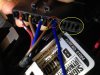
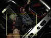
Working on a motorcycle, small dual sport
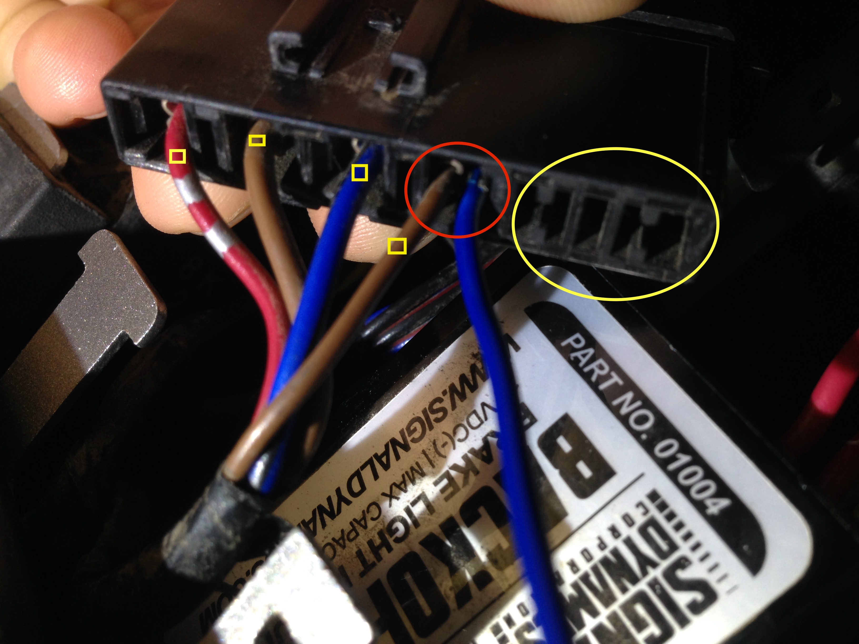

img_0482-jpg.110200


Red circle
I know I can just splice into one of the 12v wires but I think it looks nicer to use the harness.
Can I use the harness this way? ... the two wires in one slot ...circled in red in the picture

Yellow circle
The slots in the yellow circle are 10 amp spares... but I'm not sure how to use them.

(4) wires with yellow squares
Also im not sure about these (4) wires ,
they read 11.02 v on the multimeter when key is turned... but I think they should be 12v
they are the ignition , radiator fan and something else ... which I assume should be 12v.


need advice thanks
 

Attachments

  • IMG_0482.JPG
    IMG_0482.JPG
    1.3 MB · Views: 470
Red Circle: I think it's okay if it's securely mounted which I can't tell from the photo because I don't know if you just jammed another crimp in there (definitely not good) or if you crimped two wires into one crimp (depends on the crimp, wire sizes, and housing), or what ever else is possible.

Should probably get someone else to confirm me on this, though.
 
Last edited:
Red Circle: I think it's okay if it's securely mounted which I can't tell from the photo because I don't know if you just jammed another crimp in there (definitely not good) or if you crimped two wires into one crimp (depends on the crimp, wire sizes, and housing), or what ever else is possible.
.

theres actually two crimps in there! the original crimp (brown wire) and the after market wire+crimp (blue wire)
the after market on is a bit smaller so it was able to fit.

not 100% what a crimp is but I assume its the little metal "terminal" thing right?
 
should I remove the crimp and the push the exposed wire in there?
do you think its better to just splice?
 
should I remove the crimp and the push the exposed wire in there?
do you think its better to just splice?
No, definitely don't do that. If the housing is meant to be used with a crimp contact, then use a crimp. The only method I would use is to crimp both wires into a single contact but you will have to judge for yourself whether the two wires are sufficiently grasped by the crimp (and they may not be if a single wire is already near the crimp's AWG limit and you stick in another wire of the same AWG.)

The crimp should go around the two wires almost as if it's were a single wire. No funny business that looks very different from a normal single-wire crimp.

the wires are all connected to 10 amp fuses
im not sure how to take out the original wire
 
Oh, that's a fuse box. I thought it was a connector. Just splice it.

okay only reason why I was worried about splicing is something going wrong ...

I can easily solder and splice wires.
But I don't know much about the circuits on the bike and I'm a beginner with electrical systems in general so I don't want to mess anything up.

... the wire is 11.02 v when I turn the key and 0.0 v when off.
do you think it will be fine?
 
...
... the wire is 11.02 v when I turn the key and 0.0 v when off.
do you think it will be fine?

If there is a 12V Lead-Acid battery in there, it is likely shot. The resting voltage on any 12V vehicle ( with a lightly-loaded, fully charged, healthy lead-acid battery should be about 12.65V, higher if the vehicle was recently run and the surface charge on the battery hasn't yet dissipated. With the charging system on-line, you should see about 14.2V or a bit higher.

Is there a big load on the battery when you turn on the key, like the headlight? That might pull the battery voltage down a bit, but 11V looks worrisome...


well the battery reads 12.3 -12.4 v..
I think it was reading 11.02 v b/c I couldn't stick the multimeter prongs deep enough into the harness.
I noticed sometimes if I hold the prongs at a weird angle (for example against the battery terminals) then I get like a lower inaccurate reading bouncing between like 11.4 - 11.9 v
..and when I hold it nice and steady at a better angle it reads accurate. so it might just be a small discrepancy

A voltmeter is a high-impedance device. The reading does not depend on how hard you stick probes in holes. You seem to have some higher-than-normal voltage drops in your wiring.
 
I think this whole thing is a bad idea. You've now got two circuits pulling current from a fuse (and wire terminal and housing) that was meant for one 10A circuit. So, you're bound to blow the fuse before it would otherwise not blow.
Why not simply use the empty slots with your new circuit and put in an appropriate fuse??? All you would need is the correct terminal (what you are calling a "crimp") suitable for that housing (the black plastic thing) and a fuse. NEVER simply stuff a wire into a housing -- that's asking for all sorts of trouble!
 
Your 11v reading is probably because you are measuring it with the engine off. If the battery is anything but fully charged, a voltage drop from the lights, ignition, etc will result. With the engine running, those readings should go up to around 13 volts or even higher, sometimes depending on the RPM.
It looks like you're adding a brake light to make your bike street legal. If so, be careful what circuits you tap into. I still think it's best to have a dedicated circuit.

no its a dual sport its already legal. but yeah I noticed that almost everything on the bike are connected to one circuit.

I'm setting up a meter for an 02 sensor to tune the carb or the air fuel intake ratio.

I'm going to use and "add a circuit" to tap into this harness.


Why not simply use the empty slots with your new circuit and put in an appropriate fuse??? All you would need is the correct terminal (what you are calling a "crimp") suitable for that housing (the black plastic thing) and a fuse. NEVER simply stuff a wire into a housing -- that's asking for all sorts of trouble!

and as mentioned before I don't know how to use the spare slot but if you want to recommend a tutorial or explain how to do so I would appreciate that.
 
You'd have to use a tool to remove one of the terminals from its slot to see exactly what kind of terminal it is. It's probably a 1/4" quick-connect terminal, or something similar. These can usually be removed by carefully inserting a thin wire like a paperclip to depress the spring tab that holds it into the housing, while gently pulling on the wire end -- although there are tools made specifically for this task. If you look closely into the housing from the mating end of the housing (not the wire end), you can see the tab I'm talking about. When you get your new terminal, simply crimp it with a good crimping tool and push it into the housing until it clicks in securely.
5950x1b__07444.1396897548.1000.1000.jpg
 
Status
Not open for further replies.

Latest threads

New Articles From Microcontroller Tips

Back
Top