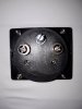
To be fair it's pretty obvious, it's a 1mA meter, and the series resistance is so high as to totally swamp the internal resistance of the meter (so that can be ignored), so it should be 150V FSD with the pot at one end, and 250V FSD with the pot at the other, +/- the tolerance of the resistors.
This takes me back to when I was a kid, we were fairly poor, I couldn't possibly afford to buy resistors or anything (never mind a meter), I used to get all my components from old TV's at a local tip - I used to write down the values I wanted, along with the colour codes of them, and go to the tip with a pair of cutters and a screwdriver, hunt for the values I wanted and cut them out.
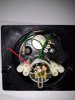
Anyway, we did about meter movements in physics at school, and shunts etc. - so I thought if I could find a meter I could make a simple multimeter. The only one I could find was an ammeter in an old car, so I though 'no problem take the shunt out, and use the bare movement' - nice idea, but when I took the meter to pieces there was no shunt, just a very thick 'coil' which passed the +/-30A directly, and a moving iron movement.