Continue to Site

Welcome to our site!

Electro Tech is an online community (with over 170,000 members) who enjoy talking about and building electronic circuits, projects and gadgets. To participate you need to register. Registration is free. Click here to register now.

  • Welcome to our site! Electro Tech is an online community (with over 170,000 members) who enjoy talking about and building electronic circuits, projects and gadgets. To participate you need to register. Registration is free. Click here to register now.

Is there any thing you would add?

Status
Not open for further replies.

Zitheran

New Member
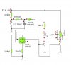
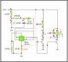
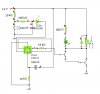
]I be leave that this circuit is good to go. Designed so you push the momentary button on the left ones and the relay coil is energized and the led illuminates, push the momentary button once more the relay coil is no longer energized and the led turns off. The compositor and two resistors on the left along with the Schmitt inverter are for denouncing the momentary push button. If there is anything that I need to change or add please let me know.
Thanks
:D
 

Attachments

  • D type flip flop.JPG
    D type flip flop.JPG
    28.1 KB · Views: 175
You don't need the 10k resistors on the 4013 S & R inputs (connect them directly to gnd).

The transistors should have resistors inline with their bases. (the 2 x 10k that you now have spare can be used here).
 
You don't need the 10k resistors on the 4013 S & R inputs (connect them directly to gnd).

The transistors should have resistors inline with their bases. (the 2 x 10k that you now have spare can be used here).

Good point. :)

And replace that 1uF capacitor with a inverse biased diode.
 
I would leave the 10K resistor from the reset of the 4013 to ground and add a 100nF capacitor from the reset pin to +12V, that way when you apply power the output (Q) would not be high. The Q output can be either high or low on power up.
I would connect the two transistors in a darlington configuration as the Q output probably won't supply enough current to drive the transistor.
I would connect the LED and it's resistor in parallel with the relay coil.
Make sure the input pins of the other F/F in the 4013 package are tied either to ground or +12V
I made some corrections to your drawing.
 

Attachments

  • modification.JPG
    modification.JPG
    131.3 KB · Views: 148
Thank you all for the fast reply’s, I made the changes that all of you suggested. I did not increase the capacitor on the de-bouncing circuit to 470 nf because I do not want to have to hold the button down for very long. If anyone has any other ideas please let me know. k7elp60, this is just one test circuit, I will have 8 push buttons altogether controlling 8 relays.
 

Attachments

  • d typy flip flop2.JPG
    d typy flip flop2.JPG
    30.6 KB · Views: 154
Status
Not open for further replies.

Latest threads

New Articles From Microcontroller Tips

Back
Top