Continue to Site
Follow along with the video below to see how to install our site as a web app on your home screen.
Note: This feature may not be available in some browsers.
Hi Mike,
I think you can use either one. But with the one more often shown on the web, the resistors R1 and R2 would have to be exchanged in order to get rid of the exponential part (and thus remove the damping required to make an oscillator).
")
Hello Winterstone,
Well would you mind if we did the circuit but with two 10k resistors and two 1.59e-8 capacitors instead? Or another combination where R3=R4 and C3=C4 because that makes the analysis much simpler. Is that circuit still a good circuit for what you want to show then?
But i assume you would prefer to see the analysis without the extra R33 and C44 right? As they are only required for the simulation right?
.
But the short answer is that the circuit will not oscillate because the pole pair is too deep into the RHP and that causes the output to saturate quickly. Limiting might solve the problem though.
Something in your calculation must be wrong - but I don`t know what (I didn`t go deeply into your formulas).
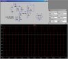
I have checked the pole location for "my circuit" and - as mentioned before - a pole pair very close to the imag. axis (RHP) and a positive real pole (deep in the RHP, causing the multivibrator behavior)
Did you try simulating this circuit?
Winterstone,
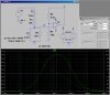
I have a more basic question. Based on the analysis or response plots for the loop gain, how can we really say that we've met the Barkhausen criteria? The linear circuit does not meet it because the gain is about 0.1 dB when the phase is zero. The condition is required to be exact. Don't we need to do a more sophisticated analysis to show that the condition is met at some point by the nonlinear limited function? In other words, as the limiting occurs, we need to prove that there is a point were we have 0 db and 0 phase.
Once we prove that, then we can look at other issues. Now, I'm not saying that an analysis won't reveal this to be true, because I haven't done it. But, isn't it important to prove this in some way before you can ask your question?