Continue to Site

Welcome to our site!

Electro Tech is an online community (with over 170,000 members) who enjoy talking about and building electronic circuits, projects and gadgets. To participate you need to register. Registration is free. Click here to register now.

  • Welcome to our site! Electro Tech is an online community (with over 170,000 members) who enjoy talking about and building electronic circuits, projects and gadgets. To participate you need to register. Registration is free. Click here to register now.

Is there a better way to do this?

Status
Not open for further replies.

throbscottle

Well-Known Member
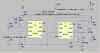
I came up with this little 2x 555 (or 1x 556) circuit to set an output high when an event happens, and then to be able to set it low again with a pushbutton even if the input event is still happening.
The input event is V3, the pushbutton is MYSW, driven by V4.
U1 is a simple bi-stable, and U2 is a momentary-switch-to-toggle-switch-converter. C2 ensures it always starts with a high output, C1 stores whatever state the output happens to be, Q1 and friends toggle the circuit back to the on state when the event is finished. Simulation works well.
It seems a bit complicated for what it does, I wondered if there is something simpler?
 

Attachments

  • Draft3.asc
    2.4 KB · Views: 89
  • triggerandcancel.png
    triggerandcancel.png
    57.9 KB · Views: 126
It's output goes high when the trigger input goes low, then goes low again when reset goes low. Oh, I tinkered with the values in-between running and uploading it. Change R5 (back) to 10k, then it works properly. Revision attached.
 

Attachments

  • triggerandcancel.asc
    2.4 KB · Views: 80
Simple? I would use a small 8 pin PIC processor and program it to do the logic you want. However, if you don't have PIC programming capabilities, then it becomes more complex. For me, a PIC is the "simple" answer....
 
seems a bit complicated for what it does,


From what I understand, you want an event to trigger the 555, then keep and hold a record that the event happened until a reset button is pressed.

Here, the 555 triggers and goes high for a short time but it triggers a two-transistor SCR that latches and holds with current flowing until a reset button is pressed.

910D1354-7CFE-4198-817E-01F40F511985.jpeg
 
Simple? I would use a small 8 pin PIC processor and program it to do the logic you want. However, if you don't have PIC programming capabilities, then it becomes more complex. For me, a PIC is the "simple" answer....

I agree, MUCH more versatile and many less components.
 
About as simple as I can get it using a 555. ;-)

118702
 
3 good solutions - thanks everybody. Micro is not really an option because I want other people to be able to build it who may be just starting out. I like yours crutschow for simplicity, but the input will (probably) be from an LDR so might not change quick enough.

Good call with the SCR, I'd thought about it before but couldn't think how to get momentary trigger. Switch might have to be N/O though, so mod needed, since posting I've gone from option of "any" to option of "tactile" Head been full of fluff for weeks, can't think straight. Sick of looking at pictures of switches... Should work with N/O if it's across the lower 10k resistor.

Heigh ho...
 
"Should work with N/O if it's across the lower 10k resistor" ... Not necessarily, with an SCR shutoff can be tricky without completely removing power.
 
Last edited:
3 good solutions - thanks everybody. Micro is not really an option because I want other people to be able to build it who may be just starting out. I like yours crutschow for simplicity, but the input will (probably) be from an LDR so might not change quick enough.

Good call with the SCR, I'd thought about it before but couldn't think how to get momentary trigger. Switch might have to be N/O though, so mod needed, since posting I've gone from option of "any" to option of "tactile" Head been full of fluff for weeks, can't think straight. Sick of looking at pictures of switches... Should work with N/O if it's across the lower 10k resistor.

Heigh ho...

I was going to post update. A NO switch in parallel with the lower 10k will do the trick to reset. Thanks Beau Schwabe !!!
 
Hmmm, it seems LTSpice is very fickle when it comes to the behaviour of the Threshold pin of it's 555 model depending on the simulation type. Hence AG's initial comment that U1 doesn't do anything. When I ran your version crutschow, it didn't work, then I noticed the uic setting. Threshold works opposite way when uic is not set. So it works now. Will try gophert's later.
 
Hello

It seems you want to set a latch that can be manually reset, and drive a load beyond what a 555 can handle(?)

So is a timer really needed? if not, here's an option.

ToggleWithReset.png
 
Last edited:
Hmmm, it seems LTSpice is very fickle when it comes to the behaviour of the Threshold pin of it's 555 model depending on the simulation type. Hence AG's initial comment that U1 doesn't do anything. When I ran your version crutschow, it didn't work, then I noticed the uic setting. Threshold works opposite way when uic is not set. So it works now. Will try gophert's later.


In theory, you can eliminate the 555 altogether in my two-transistor SRC.
 
Hi eTech, nice idea but the MAX16054 is quite an expensive option! A timer is absolutely not needed, but the 555 is a good option to try for this kind of thing because it is very cheap and extremely versatile and doesn't actually have to be used for timing purposes. Thanks for the suggestion though.
Gophert, I thought the same thing! I should be able to try it in real life before Tuesday :)

compared to 555 yes...but you get simplicity, flexibility, and for this you only need one.:)
 
Here is a two transistor SCR version that is a little bit easier to turn OFF. Q2 would be your drive transistor and should be rated for whatever load you are using. Q1 is low current and can be just about any PNP transistor. D1 and R5 are essentially your load.


**broken link removed**
 
Simple? How about 1/2 of a 4013 dual D flipflop. The event clocks in a 1, and the reset button hits the Reset input; switch to Vdd, resistor to GND. No debouncing needed on either input signal. A capacitor across the reset switch forms a power-on reset. 1 CMOS chip, 1 resistor, 1 capacitor, plus another resistor if the Event input needs a pull down.

ak
 
I have some ttl dual D f/f's somewhere. Might well be the best thing. Two tranny SCR without the 555 would need two transistors, 1 resistor and a series cap for the input so the component count is the same
 
Status
Not open for further replies.

Latest threads

New Articles From Microcontroller Tips

Back
Top