Continue to Site

Welcome to our site!

Electro Tech is an online community (with over 170,000 members) who enjoy talking about and building electronic circuits, projects and gadgets. To participate you need to register. Registration is free. Click here to register now.

  • Welcome to our site! Electro Tech is an online community (with over 170,000 members) who enjoy talking about and building electronic circuits, projects and gadgets. To participate you need to register. Registration is free. Click here to register now.

Is replacing my pulse sensor with an electronic circuit a good idea?

Status
Not open for further replies.

imane tech

New Member
Hello Community!
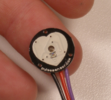
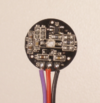
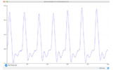
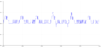
During My project of "removing motion artifacts from the PPG signal" I faced many problems related to the pulse sensor that it didn't give me any good signal, and it is for commercial use, that's why I decided to build the sensor and replace it with an electronic circuit using electronic components like resistors, transistors...I ordered another pulse sensor, but it takes time to be shipped to me, and I'm not sure if it will work well for me or not. Moreover, I don't have time to waste. I'm quite confused, what do you think? And Thank you!


Ps: That pulse sensor, I discovered that it was ruined, using a multimeter!
 
You need to explain what you're doing much better as I have no idea what you're talking about.

Mike.
My apologies! Actually, I wanna make a pulse oximeter using a pulse sensor to track the heartbeat, It is using PPG technology PPG which is a technical term for shining light into the skin and measuring the amount of light that is scattered by blood flow. That’s an oversimplification, but PPG sensors are based on the fact that light entering the body will scatter in a predictable manner as the blood flow dynamics change, such as with changes in blood pulse rates (heart rate) or with changes in blood volume (cardiac output). In fact, I got many problems getting the shape of the signal that I want to use later to calculate the heartbeat! That's why I'm asking, If I have a problem with the sensor, is it good to build a circuit that can kinda replace it completely?


Ps: I put down below the image of the sensor just to give you an idea, and the circuit.

And Thank you!
 

Attachments

  • pulse 2.PNG
    pulse 2.PNG
    304.9 KB · Views: 188
  • pulse 3.PNG
    pulse 3.PNG
    200.7 KB · Views: 187
  • circuit d'émission.PNG
    circuit d'émission.PNG
    35.5 KB · Views: 182
As far as I'm aware those sensors are reliable and effective, far more so than crude LED/photo-transistor ones - if you damaged it?, how did you damage it?.

Also, how did you test it with a multimeter?.

But the discrete sensor should work, just not as well as the modern one - but I'm dubious about the use of antique low spec opamps, and small value coupling capacitors. It's something to play with though.
 
The circuit in the schematic will not work.

You will get some grief for using an "ancient" 741, but many newer opamps will not work either. The major problem is the input common mode signal voltage range. For the 741, it does not extend down to the negative rail, which is the input signal reference potential because U1pin2 is connected to GND through R3. The opamp output will be saturated either high or low (can't remember which).

Next up is the U1 circuit. It has a gain of 101 and is DC coupled. This means that the input offset voltage (7.5 mV max.) is amplified along with the signal, creating a large DC offset at the output. Maybe not a problem in your case, but not the best design practice.

Both of these issues apply to the U2 circuit.

Also, something that is an actual problem for the 741 - noise. The overall circuit has a gain of over 10,000. That's a lot, and enough for the first opamp's noise to be an issue.

Also, the corner frequencies for the two highpass and two lowpass filters are barely one octave apart. This means that the overall gain in the center of the passband will be less than calculated.

Note: The minimum power supply voltages mentioned in the datasheet are +/-5 V. Your circuit is AC-coupled, so it can be modified to operate successfully with a single supply voltage. BUT - that voltage must be at least 10 V for reliable operation across multiple units.

ak
 
Last edited:
The circuit in the schematic will not work.

You will get some grief for using an "ancient" 741, but many newer opamps will not work either. The major problem is the input common mode signal voltage range. For the 741, it does not extend down to the negative rail, which is the input signal reference potential because U1pin2 is connected to GND through R3. The opamp output will be saturated either high or low (can't remember which).

Next up is the U1 circuit. It has a gain of 101 and is DC coupled. This means that the input offset voltage (7.5 mV max.) is amplified along with the signal, creating a large DC offset at the output. Maybe not a problem in your case, but not the best design practice.

Both of these issues apply to the U2 circuit.

Also, something that is an actual problem for the 741 - noise. The overall circuit has a gain of over 10,000. That's a lot, and enough for the first opamp's noise to be an issue.

Also, the corner frequencies for the two highpass and two lowpass filters are barely one octave apart. This means that the overall gain in the center of the passband will be less than calculated.

Note: The minimum power supply voltages mentioned in the datasheet are +/-5 V. Your circuit is AC-coupled, so it can be modified to operate successfully with a single supply voltage. BUT - that voltage must be at least 10 V for reliable operation across multiple units.

ak
Thank you so much for your precious information!

regards Imane.
 
As far as I'm aware those sensors are reliable and effective, far more so than crude LED/photo-transistor ones - if you damaged it?, how did you damage it?.

Also, how did you test it with a multimeter?.

But the discrete sensor should work, just not as well as the modern one - but I'm dubious about the use of antique low spec opamps, and small value coupling capacitors. It's something to play with though.
Thanks for your reply, actually when I used the multimeter in the output of the sensor when it is attached to the Arduino board, the number that I get isn't changing whether my finger is on the sensor or not, moreover, the signal that I get is far from what I want. My question is how can I know if my sensor is actually working or if it is damaged?


You'll find down below, some pictures of the signal that I get, and the one that I aiming for.

Ps: you'll find also the shape of the sensor!
 

Attachments

  • Clean and good ppg signal.PNG
    Clean and good ppg signal.PNG
    90.7 KB · Views: 190
  • ppg signal arduino threshold value problem.png
    ppg signal arduino threshold value problem.png
    27.3 KB · Views: 198
  • mauve truc.PNG
    mauve truc.PNG
    248 KB · Views: 190
Status
Not open for further replies.

Latest threads

New Articles From Microcontroller Tips

Back
Top