Continue to Site

Welcome to our site!

Electro Tech is an online community (with over 170,000 members) who enjoy talking about and building electronic circuits, projects and gadgets. To participate you need to register. Registration is free. Click here to register now.

  • Welcome to our site! Electro Tech is an online community (with over 170,000 members) who enjoy talking about and building electronic circuits, projects and gadgets. To participate you need to register. Registration is free. Click here to register now.

Is it possible to rewind a Yamaha Stator

Status
Not open for further replies.

alexisfire

New Member
Well I've been trying to use google and some motorcycle forums to find some information on rebuilding/rewinding some coils on the stator of my motorcycle and I just realized, maybe I should try finding an electronics forum instead, cause I've been having no luck yet.

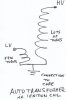
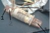
My bike doesn't have spark and I believe its because my source coil is bad, they are really expensive to replace and I want to know if I can just unwind it really carefully, counting the turns, buy the right size magnetic wire, and re-wind it exactly how it was done previously?

However, I am curious if there is anything else I need to know about the coil before I unwind it? How can I test it when I'm done (other than trying to start my bike)?

I'll provide any requested information that I can find if someone's willing to help me with this project.

Thank you!!!
 
Last edited:
I'm not familiar with the Yamaha but I'd say yes, I've re-wound the magneto for a Polaris and Arctic cat snow machine, But that was about ten years ago,
 
Have you used an Ohmmeter to check the resistance of the winding? Open or infinite Ω means the coil wire has become disconnected. A few tens to a hundred Ω means that the coil is still connected. Are both ends of the coil isolated from the iron core? If so, use the Ohmmeter to check to see if the coil is shorting to the core internally?
 
Rewinding is not that hard. It is however very time consuming in most applications!

Got a good picture we could see?

If you do go the rewind route, pick up a can of electric motor and transformer sealer from a electric motor rewind shop. When your done and everything checks out and works again, spray it down good. You want to get it into the windings the best you can and make sure everything is bonded together again.
This works best!

Clear coat acrylic enamel spray paint works well too, If the operating temperatures are not too high. And for high temp use the high temp rated barbecue spray paint will work also. But it needs several layers to get a good solid bond in most applications.
 
Thank you all for the quick answers! I'm really impressed and estatic now! I'm out of town for a supercross race, but as soon as I get home I'll check the resistance of the coils, and post pictures of the stator I'm talking about!

I just wanted to say thanks! Really, I'm excited to work on this, thanks!
 
If you can't get an ohm reading, carefully unwind and count the turn you take off, If its blown open just start counting again from the open spot and add the total turns till you have it all unwound,
KEEP TRACK of how many turns are on the core that crucial so you get approx the same Voltage again, You don't have to be precise on the turns but the closer to original number the closer to factory Voltage output you will get, Wire size is another important thing you'll need to us the same size wire or the stator coil core will fill to quickly and you run out of room before you get all the turns on, If your wire is to small the resistance will be different and you won't get the current flow thats also required to fire the ignition coil/spark plug,

I used a lathe with a thumb counter attached to it and every Rev it would do the counting for me, It wasn't real hard just time consuming,
OHHH YA Also remeber to leave a tail of wire out from the start of the winding so you can do your terminations, If you bury the wire your hopped and will need to start all over,
 
Okay, I'm measuring about 230 ohms across the coil. Does that imply that the coil is still good?

Probably good.

Now measure between either of the wires and the core upon which the coil is wound. Should be infinite. If not, you coil has rubbed through (due to vibration) shorted to the core. Measuring from core to either coil end will give you an idea of where along the coil the short happened.
 
I have an open from the positive wire to the core, but on the other wire to the core I have a short. Is that not right?
 
Is this like the magneto ignition coil in my Briggs&Stratton Lawn Mower?

If it is, then the resistance from LV to core should be low, a few Ohms.

The resistance from HV to core should be higher, a few hundred to a thousand Ohms.

The resistance from LV to HV would be the sum of the two readings obtained above.


There are actually two separate windings (four ends), but two of the ends are connected to the armature core.
 

Attachments

  • coil.jpg
    coil.jpg
    99.1 KB · Views: 2,062
Last edited:
This is just the source coil responsible for generating the original current supplied to the primary side of the ignition coil. My ignition coil is a big step up transformer too, but I'm talking about my source coil. I'll try to find a basic schematic I can post.
 
This is just the source coil responsible for generating the original current supplied to the primary side of the ignition coil....

So it only has two wires?

Something is inconsistant. You said you measured 230Ω from W1 to W2. You measured a few Ω from W1 to Core. You measured infinite Ω from W2 to core.

THAT is IMPOSSIBLE if there is only one winding!
 
Last edited:
hmm, i'm going to post some pictures of the coil. I'm working on it right now. It seems like I have an open from one end of the wire to the other maybe.
 
Okay, I'm posting a picture of the coil I'm working on. It looks like point 2 is the start of the wire, is that correct possibly? Point 3 is the wire that comes out of the windings and goes off to the ignition coil.

From 1 - 2 i measure a short.
1 - 3 I measure about 250 ohms
1 - 4 i measure a short when i move the dmm's leads around in the hole's of the core.
 

Attachments

  • untitled.JPG
    untitled.JPG
    19.7 KB · Views: 829
It looks to me that your coil is ok.

1 and 4 are just the ends of the core, so a short is to be expected.

2 is electrically bonded to 1 (& indirectly to 4), so a short is to be expected.

2 to 3 is the end-to-end resistance of the coil.

If you reinstall the coil, leave wire 3 open, connect your Multimeter in AC volts mode between 3 and 1,2 or 4. Spin the crank to see if you get a small kick as the magnet moves past the coil's core.
According to the picture that you have and the descriptions of the shorts/ resistance checked, I would agree with mike on this ( the coil appears to be good ) Chances are 1 or more of your magnets have lost their magnetizm, And this is possible!!!!!!! Or the problem may be your ignition coil, you could have a short or open!! Could even be that the ground to the ignition coil has failed, Check the ignition coil before doing any more disassembling
 
I'm trying to find the ignition coil still lol, so I havn't done any testing with that yet, but I will!

I did stick a DMM across the source coil and spun the flywheel, I was reading about 3-4 AC volts. Any ideas if thats about what that coil should be reading? I can't find any specs like that.
 
I'm not sure what the specs are but I'd say everything fine with the coil, 3-4 volts isn't much but then again if the motor was running and spinning the magneto faster the voltage would be way higher, I'd be looking for another problem in your ignition system
 
Status
Not open for further replies.

Latest threads

New Articles From Microcontroller Tips

Back
Top