Continue to Site

Welcome to our site!

Electro Tech is an online community (with over 170,000 members) who enjoy talking about and building electronic circuits, projects and gadgets. To participate you need to register. Registration is free. Click here to register now.

  • Welcome to our site! Electro Tech is an online community (with over 170,000 members) who enjoy talking about and building electronic circuits, projects and gadgets. To participate you need to register. Registration is free. Click here to register now.

IRS2453 the H circuit

Status
Not open for further replies.

gary350

Well-Known Member
I built this H circuit on a project board it is powered by several D batteries in series = 14.4 VDC total.

UPDATE

I changed 10K resistor in pin 4 to 20k the osc is now running at 31.5KHz. I took readings at pin 5 & 6, 5 & 7, 5 & 9, 5 & 13.

Mosfets are not running.???


100_4278.JPG


100_4277.JPG


100_4283.JPG
 
Last edited:
you should tie SD pin to ground, don´t leave it flapping in the breeze.
 
The load coil has a very small inductance and will behave like a piece of wire (a dead short) at 90kHz.
The contacts of a solderless breadboard will smoke and burn with the very high currents if the battery can supply a high current.
 
I changed the 100 ohm resistor to 47 ohms. Now I get stupid meter readings. Meter show osc runs at 100KHz on pin 6 & 7 with the load but with load removed osc goes up to 170KHz on pin 6 & 7. Meter shows osc is 8Khz on pin 9 and 10KHz on pin 13. Meter reads 1.2KHz on the mosfets. Nothing makes sense.???

Maybe I put the 47 ohm resistors out of the circuit to see if osc is still working correctly.

OSC is dead.


100_4304.JPG
 
Last edited:
First, that's not a good application for a protoboard. There are just too many parasitic inductances, capacitances, and resistances. Use dead-bug construction.

Power bridges like this are actually quite difficult to get right and 90% of it is getting the gate drive right.

As a starting point, limit the current through the MOSFETs by adding a resistor in series with the drains of the two top switches. Likewise, for now, replace the load coil with a resistor. Then, when there is a problem, you don't blow everything up. Once you have the gate drive sorted you can take out the drain resistors out. Once you have the desired waveform appearing across the load resistor, you can change it to a coil.

The gate driver chip inserts a microsecond of dead time. But you can still get shoot-through if the MOSFETs take too long to switch. While you have the drain resistors in place, measure the voltage across them to check the shoot-through current. Smaller gate resistors will give you faster switching, but only to a point because the IC has a limited output current.

That's a 60 volt MOSFET which seems like plenty of overhead for a 12 volt system. But with an inductor in the load, you could generate more than 60 volts. Especially on a protoboard. (I once had a high-power bridge develop so much voltage across a 100 mm piece of 00 copper wire that it shot sparks across a couple cm gap.)

Unfortunately, you have a tradeoff here. Faster turn on and turn off will cause bigger voltage spikes from the inductances in the circuit (especially the protoboard). But slower turn-on and turn-off result in higher power dissipation in the transistors. Higher edge rates also make EMC problems more severe but you probably don't care about that at this point.

As someone else said, driving the pictured coil with 12 volts with a 35 KHz square wave is a non-starter. You will either need a higher inductance coil, or a much higher drive frequency. Protoboards are useless at the frequencies it would take to drive such a coil with 12 volts. What are you actually trying to achieve?

This is a learning project. I am building a better induction heater than I already built. Ok I need to get my energy back and get to feeling better before I work on this project I been in the hospital with the diarrhea virus. Doctor was putting liquid in me with 2 IVs almost as fast as it was squirting out. I have not been this sick in 25 years, wife had the virus too she got it a few days after me. Doctor said, hospital is full of stomach virus patients but no covid patients in here for a month. Doctor said, it will take you 2 months to get your energy back. I need to buy another IRS2453. The first IRS2453 was running at 90KHz with nothing connected to it. When I connected other parts it died. I have a blank PC board I can solder parts too. Do you have parts value suggestions?
 
100 ohms on all 4 gate resistors?

100 ohm resistor in place of the coil?

Is it ok to use a IC socket to plug in the IC if it smokes it will be easy to replace?

Do I need to worry with high KHz part interference with with other parts?
 
Plan on putting a .1 uF ceramic disk along with a tantalum on protoboard
to bypass the supply (batteries) and make it more stable.

Use low esr bulk cap, tant minimum, polymer tant best.

1653498478914.png


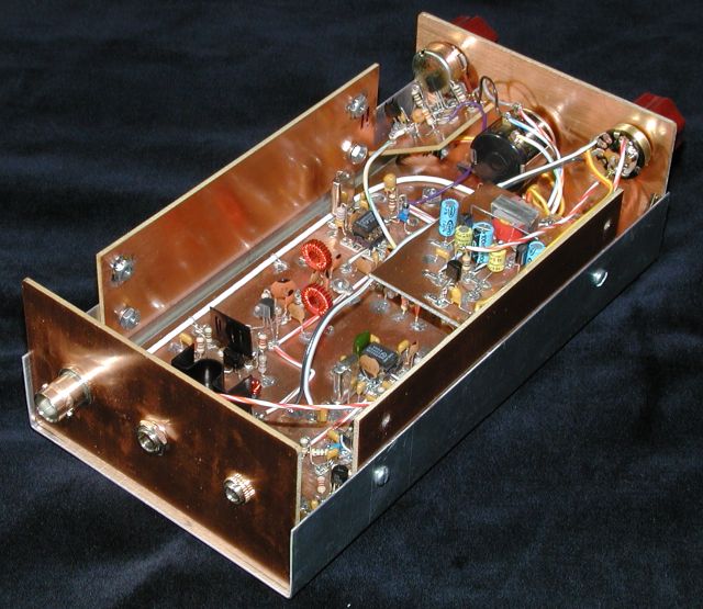
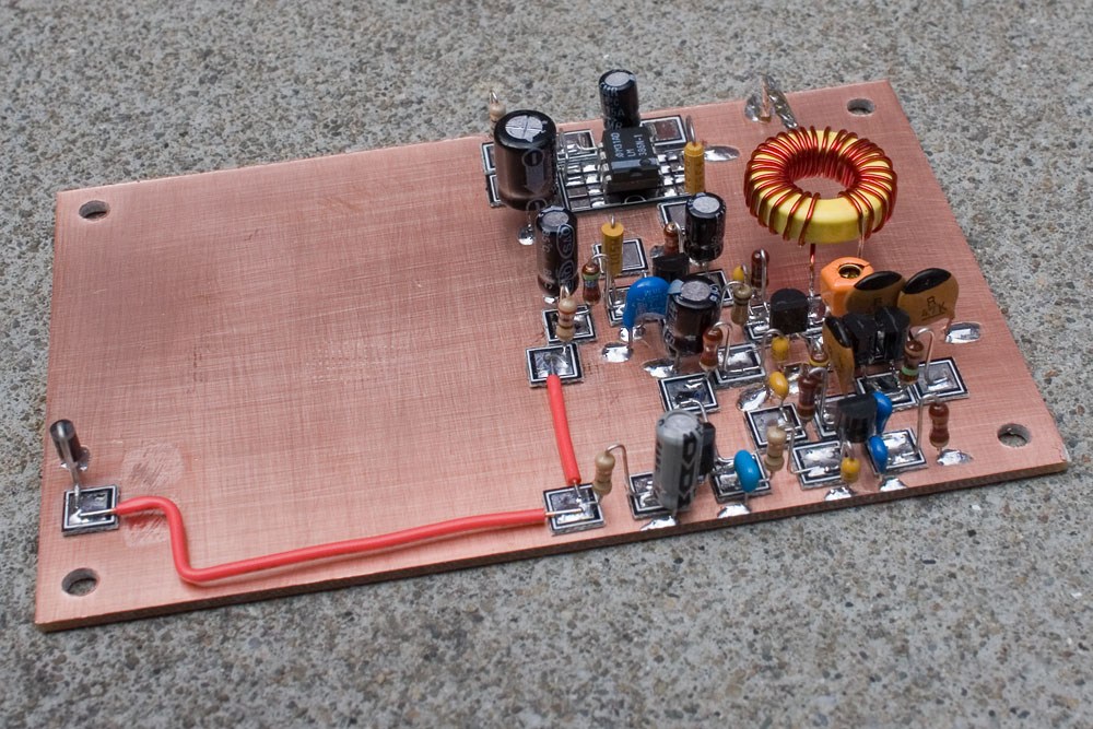
Getting low L circuit results, and stiff grounds, "Manhattan" construction technique -


Guessing you should have heat sink clips on MOSFETs.....


Regards, Dana.
 
Last edited:
A solderless breadboard does not work for high frequencies and/or high currents.
 
I meant use 100 ohm resistors for the load (the coil) and between the high-side drains and V+
Gate resistors need to be small. Divide the gate drive voltage by the gate driver's current rating as a first guess. Go down from there. You really need an oscilloscope for this kind of work.
 
Yeah, I second the suggestion for Manhattan style. Ive also used a poor man's version where you Dremel gaps in the copper to create isolated islands instead of gluing on blocks.

For an h-bridge, you want a wide block or island for V+ and bridge the gap to ground with some capacitors. I frequently use 10uf 100v 5750 chips for this. Mount small blocks/islands halfway up for the ends of the inductor. Try not to use any wire other than the transistor leads within the bridge.

Also, (can't see his name while I'm typing on my phone) is right about the heatsinks but you can worry about that when you get a little farther down the road. When you remove the 100 ohm resistors I suggested, you'll be ready for some kind of heatsinking.

Good choice for a learning project. This sort of circuit teaches you that lines on a schematic aren't pure 0 ESL 0 ESR paths in the real world.

Keep the loop from driver output, to gate resistor, to gate, and from source back to driver ground as compact as possible. Minimize area enclosed by this loop and minimize wire lengths within it.
 
Status
Not open for further replies.

Latest threads

New Articles From Microcontroller Tips

Back
Top