Continue to Site

Welcome to our site!

Electro Tech is an online community (with over 170,000 members) who enjoy talking about and building electronic circuits, projects and gadgets. To participate you need to register. Registration is free. Click here to register now.

  • Welcome to our site! Electro Tech is an online community (with over 170,000 members) who enjoy talking about and building electronic circuits, projects and gadgets. To participate you need to register. Registration is free. Click here to register now.

iron core saturation

Status
Not open for further replies.

MacIntoshCZ

Active Member
Hello there,
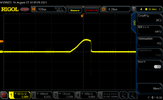
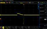
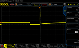
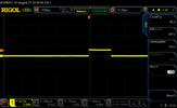
where do you think the core is saturated? Thanks
RigolDS8.png

Its hard to determine where i should place cursors.
 
Last edited:
VCC is 11,2V, current sense resistor is 1,5R., core area is aprox 70mm2, turns = 10
If you consider those values i got as results:
L = VCC*time/(Ursense/Rsense) = 11,2*2,6*10E-6/(2,83/1,5) = 15,5uH
Bs = L*(Ursense/Rsense)/(Turns*Area) = 15,57*10E-6*(2,83/1,5)/(10*70*10E-6) = 42mT

42mT is really low value.
 
Last edited:
Circtuit? what are you measuring there?
Měřím na R4, Prostě snímám napětí rezistoru, přepočítávám na proud.
Measuring on R4. But there is no need for showing circuit.
1629974537196.png
 
There is no saturation in that screenshot. If there were, the rate of rise of current would start increasing instead of decreasing. This looks like a normal response of RL circuit, where the current increases exponentially up to Vcc/(Rsense +Rinductor)
 
Its not as clear as measuring on ferrite coil. My R4 is gonna smell horribly if i increase it a little bit
1629974938967.png
 
The B/H graph is a completely different thing to what you are measuring. If there was saturation the graph would look like this
1629975547620.png


The pulse is quite short, you can let it run for say 100us and the resistor will be fine, just repeat the pulse only every second or so. You will see the graph tapers off at 11.2V.
 
Green is core with no saturation, blue is with saturation. You can see how the current starts rapidly increasing at one point.
1629976325990.png
 

Attachments

  • saturation.asc
    668 bytes · Views: 189
thanks for info, I changed R4 from 1R5 to 0.1R. Still looks linear.
Now its different story.
Now 1Tesla without saturation
RigolDS9.png
 
I need better device. Just few pulses. This takes like 20W. Looks like task for MCU.
Or even better - just lower frequency to something like 100Hz
 
Last edited:
How about an 555 oscillator at 1Hz triggering a monostable 555 one-shot with small duration like 100us, then a gate driver, for example IR2113.
 
How about an 555 oscillator at 1Hz triggering a monostable 555 one-shot with small duration like 100us, then a gate driver, for example IR2113.
I am actually using ir2153. I chose 6,8M Resistor for R_off (biggest i found) CT is 10nF, Now i have 15Hz aprox.
 
I am starting to hate emf / emi what else....
I am again suffering with non-saturating coil.
When i connect it to two different powersupplies, 15Hz frequency works but it looks strange.
When i connect it only (that means power part and control part have same vcc) to second PSU (laptop charger) it starts to oscillate on 2khz frequency. i though it has not enough power, I added 15mF (yes mili) cap to VCC. No differents
Those experiments makes me love electronics...
dog-doge.gif
 

Attachments

  • coil current.png
    coil current.png
    81.9 KB · Views: 196
  • coil.png
    coil.png
    76.2 KB · Views: 206
  • DS_mosfet.png
    DS_mosfet.png
    75.7 KB · Views: 194
  • gate.png
    gate.png
    73.2 KB · Views: 187
Last edited:
Worth mention that current is 82A!!! Its measured on 10miliohm resistor. And it with 10x times probe.
In this case Bsmax is 1,5Tesla. Maybe mosfet do not like high current pulses? =) Also 82A could cause some voltage drops.
I am using if3205
1630080215649.png
 
Status
Not open for further replies.

Latest threads

New Articles From Microcontroller Tips

Back
Top