Continue to Site

Welcome to our site!

Electro Tech is an online community (with over 170,000 members) who enjoy talking about and building electronic circuits, projects and gadgets. To participate you need to register. Registration is free. Click here to register now.

  • Welcome to our site! Electro Tech is an online community (with over 170,000 members) who enjoy talking about and building electronic circuits, projects and gadgets. To participate you need to register. Registration is free. Click here to register now.

IRF510 Mosfet Circuit

Status
Not open for further replies.

ddevun

New Member
Hi, I'm working on a project, and I've drawn up a schematic that I want to make sure it will work before I put it together. I'm a novice, so bear with me.

I have an exercise bike that hooks up to a digital display. the wire can be unhooked from the display. Inside the wire from the bike wheel is two contacts. The resistance across the contacts is about 1meg when the wheel is turning, and an open circuit when the wheel is still.

My goal is to hook that up to a game controller, so that when the wheel is turning a button is pressed, and when the wheel stops the button is let up. It seemed simple at first, except 1meg is way too much resistance for the controller to be able to detect the button being pressed.

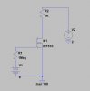
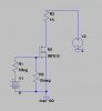
So, what I've done is created a circuit using an IR510 Mosfet, as seen attached to this post. R1 represents the exercise bike (remember, it's an open circuit when the bike isn't moving), V2 is the measured voltage across the open circuit of the button, and V1 is a 9 volt battery.

The idea is, basically, the wheel on the exercise bike will start turning and apply 9v to the gate. this will open the circuit across the button on the game controller, and the game controller will detect the button as being pressed.

I would really appreciate an expert opinion on this circuit before I get the parts to put it together. It seems to work in LTspice, but I want to make sure.

Thanks, Donnie
 

Attachments

  • bikeschematic.jpg
    bikeschematic.jpg
    10.5 KB · Views: 1,782
ok, after doing some reading, I found an error in the schematic. This is the corrected one (a 10 meg resistor connecting ground to gate).
 

Attachments

  • bikeschematic2.jpg
    bikeschematic2.jpg
    16.4 KB · Views: 1,075
1meg and 10 meg resistors on the gate? How about 1k and 10k? With resistances that high your turn on and off times are going to be horribly slow.
 
1meg and 10 meg resistors on the gate? How about 1k and 10k? With resistances that high your turn on and off times are going to be horribly slow.
In his first post, he said the source resistance is 1Meg (which sounds suspect to me, but what do I know?).
If he doesn't need speed, 1Meg/10Meg shouldn't be a problem.
 
Yeah 1 meg source resistance from an exercise bike at 9 volts does sound a little weird. We're just shooting in the dark without more details. I guess it doesn't matter much anyways, he's only switching 2 volts across 1k of resistance, this is massive underkill for an IRF510 as it can switch almost 5 amps, and dissipate plenty.
 
the 9v is an external battery that I'm adding whose sole purpose is to drive the gate of the mosfet. The actual electronic display from the exercise bike has been disconnected from the circuit. Basically, the wheel has a wire running from it, which changes resistance across the leads depending on how fast you pedal. this wire normally plugs into an electronic display; I've discarded that for the purposes of this project. Instead, I plan to use the leads from the wheel as a high resistance switch, as seen in the schematic.

It could be that I measured the resistance from the wheel wrong, but it shouldn't change the basic design of the project; I'll just have to play with different values of R3 if I measured wrong.

As for the IRF510, it was chosen simply because it's the only one I can buy locally; I'm pretty much limited to Radio Shack where I live. I've been thinking about it, though, and I may actually order a logic level mosfet, discard the 9v battery, and use the 5v from the USB inside of the controller.
 
I'm fairly certain that whatever kind of sensor is attached to the wheel to measure speed is not related to resistance, just because your meter was giving you a value doesn't mean you were using the meter right. Typically speaking the output from something like that would be pulses which the display it was hooked up to would translate into a speed, you can't simply attach it in the manner you describe and expect it to work. Another possibility is that the the signal coming from the wheel was simply a voltage from a small electric motor used as a tachometer. In either case the mosfet in your circuit is probably going to stay on all the time and that's about it. Either that or the applied 9 volts from the battery is going to harm whatever sensor/circuitry is in the wheel that does the measuring, you can't just put it in series with a 9 volt battery and expect it to be happy.
 
Last edited:
Yeah, you're probably right. I'm naive in the ways of stuff like this, but then that's why I posted here, to get others' opinions. Regardless, I'm sure there's a way to capture the signal; it's probably over my head, though.

I've searched for any information I can on the bike, but as far as I can tell something like this has never been tried before; not with this bike, anyway.

Thanks for the info.
 
Hook the wires coming from the treadmill up to a small speaker, like what you'd rip out of a cheap desktop radio or maybe a set of headphones. Wind the bike up a bit and see if you get any kind of sound coming out of the speaker.
 
Status
Not open for further replies.

Latest threads

New Articles From Microcontroller Tips

Back
Top