Continue to Site

Welcome to our site!

Electro Tech is an online community (with over 170,000 members) who enjoy talking about and building electronic circuits, projects and gadgets. To participate you need to register. Registration is free. Click here to register now.

  • Welcome to our site! Electro Tech is an online community (with over 170,000 members) who enjoy talking about and building electronic circuits, projects and gadgets. To participate you need to register. Registration is free. Click here to register now.

Ir transmitter problem

Status
Not open for further replies.

Miltaridis

New Member
Hi there i am currently working on an a assignment of creating a infrared link and have the following problem while trying to create the transmitter .

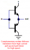
I have a 5v exit from a 4000 series ic in the form of a square wave and i use this current to drive a 2n3904 transistor which is connected as a common emitter which itself drives an ir led . The problem is that when the input's frequency gets higher than 256khz i dont get a clear waveform while measuring the voltage on the resistor protecting the led . can anyone give a tip about this ? Thank you
 
What current are you driving through the IR LED?
What voltage is the resistor-LED in the collector of the 2n3904 connected to?
 
I think the transistor turns on the LED quickly but nothing turns it off quickly. So the capacitance of the wiring and of the IR LED turn it off slowly. Use a complementary pair of emitter-follower transistors that pull up and pull down very quickly. They are also used to quickly charge and discharge the high gate capacitance of a Mosfet.

The output current from ordinary CD4xxx logic is only a few mA when the supply is only 5V so a current-limiting resistor is not needed at the input of the transistors.
 

Attachments

  • complementary transistors.PNG
    complementary transistors.PNG
    13.3 KB · Views: 206
I think the transistor turns on the LED quickly but nothing turns it off quickly. So the capacitance of the wiring and of the IR LED turn it off slowly. Use a complementary pair of emitter-follower transistors that pull up and pull down very quickly. They are also used to quickly charge and discharge the high gate capacitance of a Mosfet.

The output current from ordinary CD4xxx logic is only a few mA when the supply is only 5V so a current-limiting resistor is not needed at the input of the transistors.

i ll think i give this a try tomorrow and i will see , Can i use teh 2n3906 for the other one or you have something better to purpose?
 
10. A 2300-V 400-hp 60-Hz eight-pole Y-connected synchronous motor has a rated power factor of 0.85 leading. At full load, the efficiency is 85 percent. The armature resistance is 0.4 Ω, and the synchronous reactance is 4.4 Ω. Find the following quantities for this machine when it is operating at full load:
(a) Output torque
(b) Input power
(c) motor speed
(d) back EMF, Ec
(e) armature current, IA
 
3. A wye-connected load of three 10 Ω resistors (power factor = 100 percent) is connected to a 208 V three-phase supply. Find the voltage applied to each resistor, the line current and the total power used.

4. A delta-connected load draws 28.8 kW from a three-phase supply. The line current is 69.2 A, and the power factor is 80 percent, lagging. Find the resistance and the reactance of each phase.
 
6. A shunt motor connected to a 120 V line runs at a speed of 1200 rpm when the armature current is 20 A. The armature resistance is 0.1 Ω. Assuming constant field flux, what is the speed when the armature current is 50 A?
 
6. A shunt motor connected to a 120 V line runs at a speed of 1200 rpm when the armature current is 20 A. The armature resistance is 0.1 Ω. Assuming constant field flux, what is the speed when the armature current is 50 A?

Is this a not so thinly veiled attempt at getting us to do your homework?
 
i ll think i give this a try tomorrow and i will see , Can i use teh 2n3906 for the other one or you have something better to purpose?
I am in North america so I use 2Nxxxx transistors instead of European BCxxx transistors.
The 2N3904 NPN and 2N3906 PNP transistors are good for up to 150mA.
The 2N4401 NPN and 2N4403 PNP are good for up to 400mA.
 
well tried your schematic and it works mcuh better not so good at 2mhz but good enough at 1mhz . Still i have a question how can i calculate the current that will pass through the led ? i mean how can i calculate the resistance of the 2n3906 from emitter to collector ?
 
You still have a resistor in series with the LED to limit the LED current, don't you? Just measure the differential voltage between the ends of the resistor. I=E/R
 
Last edited:
Status
Not open for further replies.

Latest threads

Back
Top