Continue to Site

Welcome to our site!

Electro Tech is an online community (with over 170,000 members) who enjoy talking about and building electronic circuits, projects and gadgets. To participate you need to register. Registration is free. Click here to register now.

  • Welcome to our site! Electro Tech is an online community (with over 170,000 members) who enjoy talking about and building electronic circuits, projects and gadgets. To participate you need to register. Registration is free. Click here to register now.

IR Receiver

Status
Not open for further replies.

gramo

New Member
Thanks for you're help with the transmitter, now its time for the Receiver :eek:

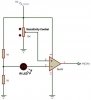
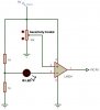
The application is to record the speed (time between signals) from a reflective device on a rotating disc. The Transmitter and Receiver will face the disc with some cardboard directly isolating the two.

The pot offers sensitivity control of the receiver circuit for use in other applications.

I should also point out that I'm using the same IR LED emitter, and working off its low impedance with the same light spectrum present
 

Attachments

  • ir rx 3.JPG
    ir rx 3.JPG
    16.4 KB · Views: 757
A photodiode, phototransistor or light-dependent-resistor detects IR. Maybe an LED like you have detects a little but I have never tried it.

You don't show the polarity of your LED.
The inverting input of the opamp is floating so its output voltage is anything.

The minimum supply voltage of a TL072 is 7V so it probably does not work with only 5V. Its output low voltage might be +1.2V and its output high voltage might be +3.8V with such a low supply voltage.
 
audioguru said:
You don't show the polarity of your LED.
The inverting input of the opamp is floating so its output voltage is anything.

The anode/cathode are hard to make out, but they are there non the less
The two resistors before the IR LED provide a voltage divider, giving 2.5V at the anode of the LED. This is enough to turn on the LED (only just driven on due to the high input impedance of the op-amp)

This leaves around 1 to 1.5V at the cathode of the IR LED (input to the -ve of the opamp)

As IR Light saturates the IR LED, it will 'turn on' more (the voltage drop will increase over it) reducing the voltage to the input of the op-amp.

At a threshold defined by the sensitivity pot, the op-amp's output will go high when the IR LED detects IR Light.

The minimum supply voltage of a TL072 is 7V so it probably does not work with only 5V. Its output low voltage might be +1.2V and its output high voltage might be +3.8V with such a low supply voltage.

Thanks, I was using the LM324, and did a quick change to the TL072 as I posted (with the thought in mind that someone was going to pay me out for using such an old op-amp :eek:

I dont want to go outside 5V for the mean time, so I'll revert back to the LM324
 

Attachments

  • IR RX.JPG
    IR RX.JPG
    19.1 KB · Views: 404
Last edited:
gramo said:
The anode/cathode are hard to make out, but they are there non the less
Why not draw things that can be easily seen?? Nearly black on black? Try black on white.

The two resistors before the IR LED provide a voltage divider, giving 2.5V at the anode of the LED. This is enough to turn on the LED (only just driven on due to the high input impedance of the op-amp)
The LED won't turn on since the TL072 has FET inputs so it doesn't have an input current, and the LM324 has PNP inputs that source (not sink) current so the LED will be reverse biased.

The inverting input of the opamp floats. If it is an LM324 then it will float up to near the positive supply and cause the output to go to ground.

As IR Light saturates the IR LED, it will 'turn on' more (the voltage drop will increase over it) reducing the voltage to the input of the op-amp.
The LEDs that I have tried perform like a solar cell and produce a small voltage. I don't know if your LED is sensitive enough to be used as an IR light detector.

I was using the LM324, and did a quick change to the TL072 as I posted (with the thought in mind that someone was going to pay me out for using such an old op-amp
Antiques are fun to see how old and how bad they are.
 
Wow, I'll scratch that idea...

Perhaps a logic IR detector like PNA4611M00XD-ND from digikey.com would do the trick?

It will detect 36.7KHz(Easly Generated by the PIC) 940nm IR, and will provide logic signals providing it can detect the modulated IR from the TX.

Leads to another question, will the TX circuit handle those speeds? I'm thinking that the PWM signal will not allow the transistor to turn on and off fast enough to allow peak power from the TX IR LED
 
Last edited:
You didn't attach the datasheet for the Japanese IR receiver and Panasonic's website has never heard of it. Digikey had only its price.

European IR receivers reduce their gain when the IR modulation is continuous so that they have less interference from 40kHz compact fluorescent light bulbs.

You switch topics so much that I can't find your IR transmitter.
 
audioguru said:
You didn't attach the datasheet for the Japanese IR receiver and Panasonic's website has never heard of it. Digikey had only its price.

European IR receivers reduce their gain when the IR modulation is continuous so that they have less interference from 40kHz compact fluorescent light bulbs.

You switch topics so much that I can't find your IR transmitter.

Sorry, thought it should go in a separate topic, here the other one - IR Transmitter

I went with the 'lower frequency' just because I thought it would be easier to produce, but a 40Khz should be too hard with a PIC anyhow. With that in mind, this IR should do the job; PNA4602M-ND from digikey.com

940nm, 40Khz IR detector with a logic output (and a datasheet :eek: )
 
Mouser carries a small line of light-to-voltage converters by TAOS. They are in TO-92 packages with three leads - V=, com, and signal. Response is pretty broad - 350 - 1050 nm. Rise times as low as 3 microseconds. All for $1.26 to $2.88. Figure out a filter and get a huge signal.
 
Status
Not open for further replies.

Latest threads

New Articles From Microcontroller Tips

Back
Top