Continue to Site

Welcome to our site!

Electro Tech is an online community (with over 170,000 members) who enjoy talking about and building electronic circuits, projects and gadgets. To participate you need to register. Registration is free. Click here to register now.

  • Welcome to our site! Electro Tech is an online community (with over 170,000 members) who enjoy talking about and building electronic circuits, projects and gadgets. To participate you need to register. Registration is free. Click here to register now.

IR IC: SFH506 or TSOP17

Status
Not open for further replies.

giftiger_wunsch

New Member
Hi guys,

I'm planning on making an RS232-interface IR receiver to use with LIRC on my home media server, but my usual electronics supplier doesn't seem to have the IR receiver IC required by the schematic I found online.

Does anyone know where I might be able to obtain an SFH506 or TSOP17 chip, preferrably a UK supplier?

I've attached the schematic for the device.


Thanks in advance for any help.
 

Attachments

  • Universal IR Receiver - Serial Port.gif
    Universal IR Receiver - Serial Port.gif
    6 KB · Views: 1,206
Last edited:
Thanks for the tip; as it happens, I did recently disassemble an old VCR. However I had another look at the board and there only appear to be a two ICs on the whole board, one appears to be a timing IC (L51DC), and the other is a very small 4-pin IC towards the back of the board which seems unlikely to be related to the infra-red functions. I haven't been able to identify the infra red components; perhaps that's just my inexperience with electronics though. I've attached photographs of the board; if someone could point out the components related to the infra-red I would be grateful. Please ignore the backdrop

In the meantime though, it seems unlikely that I'll be able to use any of the components in the device I would like to build, especially as the board has been left out in the rain for a few weeks as I thought I would have no further use for it...
 

Attachments

  • IC.jpg
    IC.jpg
    513.2 KB · Views: 557
  • overview.jpg
    overview.jpg
    2.9 MB · Views: 617
  • front section.jpg
    front section.jpg
    1.5 MB · Views: 563
Last edited:
Alright alright, obvious to someone who knows what they're looking for :( thanks for the info. I'll go take a closer look at that now.

Edit: Okay I just had a homer simpson D'OH moment when I turned the board slightly and noticed that I could see the photodiode component from the new angle. It doesn't appear to be controlled by an IC though, and it seems to have several different components, so it doesn't look like I'll be able to salvage this. I think I may have an old TV somewhere, I'll see if I can salvage the required component from that.

While I'm talking about TVs, I've never taken one apart before and I understand that they have components which are capable of acting as very large capacitors and store enough charge to pose a danger - do you have any advice for disassembling a TV?
 
Last edited:
Alright alright, obvious to someone who knows what they're looking for :( thanks for the info. I'll go take a closer look at that now.

Edit: Okay I just had a homer simpson D'OH moment when I turned the board slightly and noticed that I could see the photodiode component from the new angle. It doesn't appear to be controlled by an IC though, and it seems to have several different components, so it doesn't look like I'll be able to salvage this. I think I may have an old TV somewhere, I'll see if I can salvage the required component from that.

It's not 'controlled' by an IC, it IS an IC, mounted off the board in that plastic fitting, with the three pins running down to the board.

Incidently, that's a Samsung VCR PCB - althoough it's used by many other 'manufacturers' as well, including Sony and Toshiba.

Bit more info - the IR receiver has TK2238 on the top of it, immediately to the left of C701.

While I'm talking about TVs, I've never taken one apart before and I understand that they have components which are capable of acting as very large capacitors and store enough charge to pose a danger - do you have any advice for disassembling a TV?

The tube can stay charged up for a while, as can the main electrolytic, those are the only sources of shock hazard, but neither are really dangerous as such.
 
Last edited:
Depending upon what you intend to salvage for your stock, there are still a couple of things left on that board which may come in handy.

PT601 & PT602 opto-interrupters may be useful if you plan on any motion control/feedback projects and the inductors L602 L603 L701 et al may also come in handy. Be careful removing the inductors though, they don't stand up to rough handling.
 
It's not 'controlled' by an IC, it IS an IC, mounted off the board in that plastic fitting, with the three pins running down to the board.

Oh I see. Thanks for the info, perhaps I should have had a better look at it. I'm used to ICs looking like.... ICs. By the way, by 'controlled' by an IC, I meant that at first glance it didn't appear as though the infra red components of the board were actually handled by an IC, it appeared as though it was a collection of more basic components and that it was being handled by various circuits on the board. I'll take a better look.

that's a Samsung VCR PCB - althoough it's used by many other 'manufacturers' as well, including Sony and Toshiba

Indeed, the VCR is a toshiba.

Mickster said:
PT601 & PT602 opto-interrupters may be useful if you plan on any motion control/feedback projects and the inductors L602 L603 L701 et al may also come in handy. Be careful removing the inductors though, they don't stand up to rough handling.

Thanks for the information! I'll see if I can salvage any of these parts, and then hope that they haven't already been destroyed by being left in the rain for so long... if and when I do disassemble the TV, I think I'll check back with you guys before I throw out a board containing parts which could be useful in future, if that's okay with you ^_^


By the way, now that I know what an IR IC is meant to look like, I think I probably could have saved some time. I believe this is also an IR IC, correct? (See photo)
 

Attachments

  • IR IC.jpg
    IR IC.jpg
    71.4 KB · Views: 379
Last edited:
By the way, now that I know what an IR IC is meant to look like, I think I probably could have saved some time. I believe this is also an IR IC, correct? (See photo)

Yes, that's correct - if you're taking it out of something, it's a good idea to check the connections while it's still in circuit, they aren't always the same.
 
Yes, that's correct - if you're taking it out of something, it's a good idea to check the connections while it's still in circuit, they aren't always the same.

Yes, I was planning on doing so as I'd heard the pins often vary. Though that may be slightly complicated by the fact that it's in a device which plugs into a playstation's controller port, and gets its power that way. There does appear to be a small capacitor connected across the centre and right-hand pins however, which I'd imagine is to smooth the voltage from the power supply; so that seems to suggest those are the supply pins. Which is which may be a little more difficult to determine though. Any suggestions? Edit: I'll try taking a multimeter to it to test impedance and if that doesn't reveal anything I'm stumped :eek: 
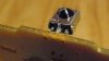
Second Edit: 3M resistance with positive in the middle, 0.3 ohm resistance the other way round. I'm guessing that probably means the middle pin is the GND pin.

I apologise for the nooby questions but I've only recently started using electronics. I'm eager to learn though :p
 
Last edited:
Status
Not open for further replies.

Latest threads

New Articles From Microcontroller Tips

Back
Top