Continue to Site

Welcome to our site!

Electro Tech is an online community (with over 170,000 members) who enjoy talking about and building electronic circuits, projects and gadgets. To participate you need to register. Registration is free. Click here to register now.

  • Welcome to our site! Electro Tech is an online community (with over 170,000 members) who enjoy talking about and building electronic circuits, projects and gadgets. To participate you need to register. Registration is free. Click here to register now.
Status
Not open for further replies.

BManriquez

New Member
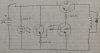
I'm trying to make a simple IR circuit that energizes a coil when the detector "sees" the beam (refer to attached schematic). The problem is when the everything is active, I have almost no current at the coil. Why am I losing so much current? I suspect it's because the base of the NPN transistor is pulling through the variable IR detector transistor and there is a loss. Does anyone have a better way to do this?
 

Attachments

  • IR Circuit.jpg
    IR Circuit.jpg
    58.1 KB · Views: 268
You may not want that sort of ckt depending on your application.
Typically, you would modulate an IR LED and use a vishay IR receiver IC and check for the lack of modulation if your doing long distance beam break detection.
 
The IR detector is only about an inch away from the emitter (mounted on a moving arm), so distance shouldn't be a problem. I just need the coil to energize temporarily when the arm passes by. I'll try this circuit modification out and see how it works. Thanks!
 
The problem is when the everything is active, I have almost no current at the coil. Why am I losing so much current? I suspect it's because the base of the NPN transistor is pulling through the variable IR detector transistor and there is a loss.
No one can answer your questions.That circuit is not a circuit. With that said.
Where you have chosen to make a measurement is impressive.Your a natural.
I would really like to see the datasheets
or the manufacturer of your IR emmiter & detector along with the relay you have, only because the next set of questions you have shall be answered in detail.
 
I should have posted the parts specs - sorry about that. The emitter/detector pair came from Sparkfun.com (https://www.sparkfun.com/products/241) (P/N: SEN-0024), the transistors are basic 2N3904 and 2N3906 (NPN, PNP), and the coil is actually a hand-wound coil as part of a homemade electromagnetic (about 8 ohms on the coil). I tried out your simplified circuit design last night and it worked great. Thanks for helping me out!
 
You are very welcome!
Someone had a misconception about that circuit, and now you know how it really works. you've been through an important thought process
Going through this process many times is what it takes to understand circuits
Build lots of circuits When something doesn't work, you have a supportive group of people on the community forum to help you out.
 
What is the power source? 3 V across 8 ohms is 375 mA load current. Can the source supply that?

The 2N3906 is rated for 200 mA collector current max.

For almost 400 mA of collector current and firm saturation, you need around 20 to 40 mA of base current in the 3906. Your 23 mA of base current might not be enough, depending on the gain of the individual transistor you have.

ak
 
Hey! Analog kid your enthusiasm is very refreshing I love this place nothing but knowledgeable helpful individuals you can't beat it. I salute you.
 
nothing but knowledgeable helpful individuals

that statement means you haven't been around here long enough to deal with the rest of us.
 
I would like to see tour schematic properly redrawn. Are you sure you actually know how it should work?

Could you repost it?
 
Status
Not open for further replies.

New Articles From Microcontroller Tips

Back
Top