Continue to Site

Welcome to our site!

Electro Tech is an online community (with over 170,000 members) who enjoy talking about and building electronic circuits, projects and gadgets. To participate you need to register. Registration is free. Click here to register now.

  • Welcome to our site! Electro Tech is an online community (with over 170,000 members) who enjoy talking about and building electronic circuits, projects and gadgets. To participate you need to register. Registration is free. Click here to register now.

iPod audio amp

Status
Not open for further replies.

-Simsy-

New Member
hi, firstly, nice forum :) iv been on it about an hour already :p
ok, so im building a simple stereo audio amp for an ipod inside an ipod - like the ones here:
Speaker made from old iPods - Hacked Gadgets - DIY Tech Blog
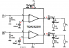
The amp i am using is the TDA2822m.
i accidentally pressed enter so the thread was posted incomplete.
continuing on... i have used 2 tantalum caps in place of 2 electrolytic caps both are 100uf. The amp currently does not work, is it because of the caps?
 
Last edited:
If your capacitors are connected with the correct polarity in the circuit shown in the datasheet of the TDA2822M and using the pcb layout shown in the datasheet and if the battery voltage is 4V to 7V then the amplifier should work fine.

But since you did not post your schematic here then we do not know what you have done.
 
thanks audioguru :)
i have used the circuit shown on the data sheet "test circuit (stereo)" http://www.datasheetcatalog.org/datasheet/stmicroelectronics/1464.pdf
im using a test voltage of 6v
and i dont have a pcb as they werent available which made things a bit tricky :eek: 
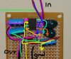
(couple of bridges) its probably the polarity. i have the arrows flowing from positive to negative. (conventional flow is used isnt it?)
this is my first actual circuit outside dodgy parallel and series differentiation types at school so go easy :p
 
The amplifiers might oscillate if you do not make them on a compact pcb with a layout like shown in the datasheet.

ST Micro show capacitors with an open line for the positive terminal and a closed line for the negative terminal.
Tantalum capacitors have the positive terminal marked with a "+" sign. Electrolytic capacitors used to be marked the same and are shown with the positive terminal marked with a "+" sign on schematics but newer ones have an arrow pointing to the negative terminal.

I marked the positive terminal on each capacitor for the stereo amplifier.
 

Attachments

  • TDA2822M capacitors polarity.PNG
    TDA2822M capacitors polarity.PNG
    23.9 KB · Views: 1,569
yep, all the caps are correct. my dads multimeter recently broke so i used an LED to see if there's any current but it wouldnt light up when placed upon the power supply pin (2) and the ground pin (4) or between speaker output (either of them) and ground. there was an active input. Does it really need no negative voltage input? thanks :)
 
Last edited:
If you placed an LED between the power supply pin 2 and the ground pin 1 of the IC then the LED is blown up without any current-limiting resistor in series with it.

The LED would also blow up and maybe the amplifier iC might also blow up if you connected the LED between the output pin 1 or pin 3 and ground without any current-limiting resistor in series with it.

Your dad's multimeter would blow up if you connected it to the power supply like you connected the LED. It short-circuited the power supply.

Or your 6V power supply or battery is dead.

The TDA2822M IC does not need a negative supply voltage. The negative wire of the power supply connects to ground.
 
Here is a picture i took of the amp. I traced a couple of branches to make them easier to make sense of. Can you see any flaws?
Thanks
 

Attachments

  • Amp.jpg
    Amp.jpg
    1 MB · Views: 539
The camera on your cell phone is so bad that I cannot see anything on the photo.
If your speakers are 8 ohms then the very small value of the 100uf output capacitors cuts all bass frequencies below 200Hz.
 
i dont actually know the resistance of the speakers as like i said the multimeter is broken and they are unmarked because they're salvaged from an old vaio. How would i prevent the mangling of my tunes? here's a better quality picture.
 

Attachments

  • Amp_GoodQuality.jpg
    Amp_GoodQuality.jpg
    157 KB · Views: 314
The photo is much better but I still I cannot see how you wired the perf board.
 
heres the better quality pic with wiring marked
 

Attachments

  • Amp_GoodQuality_Tracks.jpg
    Amp_GoodQuality_Tracks.jpg
    206.9 KB · Views: 237
I cannot see what is connected to what.
For such a simple circuit I do not understand why you have wires crossed and all over the place.
 
i cant really show you any clearer. I'll show my physics teacher tomorrow and hopefully he'll be able to identify the problem. All the bridges are due to size limitations and the lack of a pcb. I saw a method of making pcb's on the forum so i'll look into that.
Thank you for your help :)
 
Status
Not open for further replies.

Latest threads

New Articles From Microcontroller Tips

Back
Top