Continue to Site

Welcome to our site!

Electro Tech is an online community (with over 170,000 members) who enjoy talking about and building electronic circuits, projects and gadgets. To participate you need to register. Registration is free. Click here to register now.

  • Welcome to our site! Electro Tech is an online community (with over 170,000 members) who enjoy talking about and building electronic circuits, projects and gadgets. To participate you need to register. Registration is free. Click here to register now.

Inverter question

Status
Not open for further replies.

throbscottle

Well-Known Member
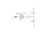
I came up with a simple idea for indicator lights for breadboarding purposes - connect a bi-directional, 2 colour LED (or two LED's in anti-parallel) and it's limiting resistor from the output to the input of an inverter. The assumption is that the DUT can sink or source the LED current, so one or the other lights depending on the polarity of the input, and the inverter provides the return path.

So the only thing I'm concerned about with this is, what happens when there is no input? There's no adequate current path to light either LED, but would the circuit oscillate? If so, what will prevent it?

DUT connects to PL1.

led-test-1.png
 
It would probably oscillate with no input. The LEDs will have capacitance, so it could lead to high frequency oscillation.

With a 3 V supply, the input threshold voltage would be around 1.5 V. The input could sit a bit below that, so the output is high, without any current flowing in the LED, so it might be stable in that condition.

Also, with no input connection, the LEDs may generate voltage from ambient light, so the behaviour may depend on the ambient lighting.

I would suggest that you put another inverter between the DUT and PL1, and then you can put a high value resistor between the input and ground to stop it oscillation if the DUT is open.
 
That was my first thought too. But then I lose the open input = no lights condition. Or am I missing something?

I was going to say ambient light voltages would cancel out, but then the LEDs are different colours so they won't completely... Never even occurred to me, that one!
 
If you want open input = no lights, I suggest this circuit:-

1617830106929.png


You can adjust the number of diodes depending on the supply voltage so that the total voltage of the LEDs and the diodes add up to more than the supply voltage, and with a floating input, no current will flow.
 
Ah, the old classic, improved! But I need to change it a bit so I can use my funky bi-directional, bi-colour LED's that I haven't got yet! So putting that in series with the input instead of each end of the PD will do the job. It's only ever expected to run on 5v so I can put 3v zeners in for the diodes.

I also realised that with a normal 3 pin 2 colour LED, the inverter circuit will work with 1 anode to it's input and the other to it's output, common to 0v, high value pullup on the input.

Since I'm making 6 or 8 of these on a small perf-board I'll just have to see what fits best.
 
Oh I've googled for logic probes lots because I've been meaning to build an actual logic probe.
No these are just a group of status indicator lights for breadboard purposes, but I want something where I don't have to worry about whether they are common anode or common cathode - just plug it in and it works, instead of plugging in a bunch of separate LEDs.
The no lights = no input was purely incidental but I decided it was worth trying to keep.
 
Would two comparators do the trick? One active if input > x, one active if input < y, and no output if between those bounds.
 
They would, and in fact there's an article here covering just that: https://diyodemag.com/projects/design_and_make_the_ubiquitous_logic_probe
But even just the straight 2 comparators is far more complicated than I want or need, considering there could be 8 of them side by side.
I'm inclined to go with diver300's circuit, altered for a 2 way LED, for my 8 (or some other number) way "logic probe". Can even get dual zeners...**broken link removed**
 

Attachments

  • led-test-1.png
    led-test-1.png
    17.9 KB · Views: 181
Interesting, but overkill and expensive (especially needing 8-ish) for a glorified LED indicator!
 
Right, so a variant of the inverter based version which would actually give me a tri-state indication. This is the most complex I'm prepared to go with it. Also these LEDs seem to be a bit cheaper than the 2 pin dual ones. (I already have more 74HC04 than I will ever need)
led-test-1.png
 
i've just realised, that's not going to do what I want, is it? Damn.
 
Status
Not open for further replies.

Latest threads

New Articles From Microcontroller Tips

Back
Top