Continue to Site

Welcome to our site!

Electro Tech is an online community (with over 170,000 members) who enjoy talking about and building electronic circuits, projects and gadgets. To participate you need to register. Registration is free. Click here to register now.

  • Welcome to our site! Electro Tech is an online community (with over 170,000 members) who enjoy talking about and building electronic circuits, projects and gadgets. To participate you need to register. Registration is free. Click here to register now.

inverter output transformer saturation

Status
Not open for further replies.
What i meant was that most converters are built to operate with a voltage output not a current output, and if you need a voltage output then you cant use a current output so there is little sense in talking about it.
Or did i misunderstand something ?
I was not talking about outputting volts or amps. (regulating voltage or regulating current)

Here is a PDF.
https://www.ti.com/lit/an/slua119/slua119.pdf
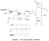
In a voltage mode PWM a OSC generates a ramp that is used to set on/off time. This functions happens with out regard to what the switch is doing.
upload_2017-4-3_20-23-18.png

In current mode, the "ramp" comes from the current building up in the switch and transformer, (no ramp from the OSC).
In current mode the current is watched nS by nS.
The output can regulate voltage or current or power, it does not matter. The point is that current and inductance is in the fast loop.
Notice the point Vs goes back to the PWM COMP.
upload_2017-4-3_20-35-43.png
 

Attachments

  • upload_2017-4-3_20-34-39.png
    upload_2017-4-3_20-34-39.png
    26.7 KB · Views: 103
Hi,

Ok that was what i was referring to as "current monitoring" which although provides some current control is not the same as what we usually call "current mode". "current mode" usually refers to a circuit that actually outputs a current not a voltage, so the circuit pictured in your diagram would be more like current monitoring.
If you look at most circuits that are considered "current mode" you'll see they operating MAINLY by current, not first by voltage and then secondary by current.

Is it just a matter of speaking? Depends who wrote the article. Perhaps you can mention where you got that drawing so we can figure out who the author is and why they are calling it current mode. I have a feeling they are just calling PART of that circuit current mode. In other words, it's not a true current mode switching converter.
 
When I get "PWM" from Power Integration, they come in different types: (referring to feed back type)
CV Constant Voltage used in DC to DC and AC to DC power supplies.
CC Constant Current used in LED drivers and LED light bulbs.
CCCV Used in battery chargers.
TI "Current Regulator " is CC, (feed back type)
Under energy harvesting there is constant power (in or out) Also maximum power point feed back.
PFC has both voltage feedback and power in feedback.
Is it just a matter of speaking?
You are right there are many different ways of saying what type of feedback is used.

The UC3842/42/44 in the data sheet "Current-Mode PWM Controllers" ( TI, ST, Cherry, Unitrode, Samsung say CM but Fairchild does not say Current Mode) same part. Most of the times when I used the 3842 the feedback was voltage, the mode is current.
Onsemi NCP1252 current mode
Linear LT1619 Current Mode
Maximin MAX5975 current mode
Fairchild FAN7602 current mode
 
Status
Not open for further replies.

Latest threads

New Articles From Microcontroller Tips

Back
Top