Continue to Site

Welcome to our site!

Electro Tech is an online community (with over 170,000 members) who enjoy talking about and building electronic circuits, projects and gadgets. To participate you need to register. Registration is free. Click here to register now.

  • Welcome to our site! Electro Tech is an online community (with over 170,000 members) who enjoy talking about and building electronic circuits, projects and gadgets. To participate you need to register. Registration is free. Click here to register now.

Inventory monitoring system..Need help in assembly

Status
Not open for further replies.

daredavel

New Member
hi guys! i've been making this project of mine in the past 3 weeks..i admit, i'm not good at assembly..may friend revise my original coding and now i'm having problem with it..:confused:..although its working..but its not finish yet.. I'm asking for all your help guys to finish the program..i would really appreciate it..

About my project:

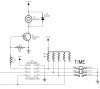
The user will set how many sensors(maximum of 12 sensors-switch type) he/she will use with the push-buttons(inc, dec).. The 7segment will display the number of sensors used and number of tools missing(0 for non..1-12 for the number of missing)..every 5secs the display changes..showing both sensors used and number of tools missing..

The leds shows if the sensors are active.. If the led is blinking, that means the tool is not placed or missing..if its in a standby lit, that means the tool is there and is detected by the sensor..

I need help in:

1) Buzzer sound - buzzer doesnt sound..and i dont know how to generate an alarm sound.

2) Buzzer Delay - if the tools are taken from the sensor the buzzer will wait for 3mins to alarm..(in the unfinished program), once the tool is taken it automatically triggers the buzzer.

3) Refresh Button - if the buzzer alarmed already, the refresh button will restart the delay before it alarm again. but the tool is returned to the sensor, it will terminate the buzzer.

4) EEPROM - the setting of the user must be saved..and if the user will change the number of sensors to use..it will automatically save the setting..


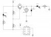
Here's my schematic guys:
**broken link removed**

Here's my Codes and Proteus Simulation, so that you can see it in actual:
**broken link removed**


I hope you could help me guys! i would really appreciate it if someone could help me finish the program! i really need your help! :(
 
I'm an AVR man myself, but I can help you somewhat, although, I really don't like pics. I don't have any pic development tools so I can't use the .rar file that I am assuming is your code. If you have an ascii listing, or generate one when you next compile, I can look through that. I can help you with your hardware.

1) I don't see any base resisitors on your transistor drives. 220 ohm - 1K.
2) what type of buzzer are you using? Is it 5v? Can it work on 20-40mA (probably not)? You should have a transistor driver on that just the same as you have on your LEDs. Some piezo buzzers have a built in oscillator, some don't. Those you have to turn on at off at their resonant frequency, probably somewhere around 2KHz.

3) R28, 29, and 31 are probably not needed... what are they used for? Looks like to pull up the 'node' when the transistors turn off.
 
Thank you for the reply sir! i should put resistors on the 'base' pin of the transistor..is that correct sir? Im using a peizo buzzer 5v sir.. How can i get an ascii file in the assembly sir?
 
most assemblers have a switch to create a 'listing' file (*.lst), or short of that you can copy the text and paste it into a wordpad file and save as ascii text...

what part number is your piezo? 12V piezos draw a good chunk of current, 5V would draw more for the same dB output (sound level)... here's how I drive mine... just replace the +12V with +5V. It should drive the buzzer ok, but you may need a low on resistance FET. This is a cheap piezo so it has to be turned on and off at it's resonance frequency, 2KHz...

I don't have any PIC development tools, sorry, I don't like them. I use AVR parts (much better)... but I'm not against putting them on my clients' boards, if that's what they really (really) want...
 

Attachments

  • piezo..JPG
    piezo..JPG
    49.2 KB · Views: 354
Last edited:
I've modified the schematic for the piezo to use the same transistor as you already have on the board. One thing we do when we design for assembly is to reduce the part type count, fewer types of parts stocked, fewer types of parts loaded onto the inserter, less chance of getting the wrong part installed... easier to check the final assy... etc...

You can use LED1/R1 OR LED2/R2 for your alarm status LED. I prefer LED1/R1 to take the loading off the micro.

One quick note, your schematic and my first schematic gave alarm output on a high, this will change that to alarm on a low.
 

Attachments

  • PIEZO2..JPG
    PIEZO2..JPG
    42.3 KB · Views: 260
Last edited:
hello sir! instead of using transistor 2n3906..can i use uln2003A ic? i dont have enough knowledge about it.. tried to research about it, it says it somehow act as a pnp transistor.. is that right sir?
 
pnp transistor

i'm having problem with the transistor..i dont know what is the correct pin config of the 2n3906..(E-B-C) or (C-B-E)..i've tested both config..but nothing happened..the bad part, my pic16f77 was damage..i don't know why..if it has any connection to the transistor.. i also have tested it in my breadboard, without the pic to make sure first that i have correct pin assignments..still i dont know how it operates..i cant make the led lit..i can figure out the correct pin assignments.

My breadboard setup test base on my circuit(top):
5v supply
**broken link removed**
 
a 2003 is a seven channel darlington NPN... if you look a the data sheet, it gives the schematic. The ULN2xxx is a family of high current darlington drivers. There's one for TTL drive (2003), one for CMOS, etc... there are also different configurations, some PNPs.

your pnp is on the wrong end. PNPs go on the 'top' of the circuit and source current. NPNs go on the bottom. Also, in your schematic, your gate resistor (1K) is tied to the emitter, not the gate.

PNPs turn on when the gate voltage is .7V BELOW the emitter voltage.
NPNs turn on then the gate voltage is .7V ABOVE the emitter voltage.
Current flows is the direction of the arrow, which is on the emitter. You have your PNP correctly pinned, but on the bottom of the circuit. You can't turn it on unless you have a (-) (lower than ground) voltage applied to the gate.

Also, in your schematic above, if you replaced the n3906 with one channel of your ULN2003, and get rid of the 1K (extra current to sink when LED is on), your circuit would work. BUT... using a darlington to turn on an LED... what a waste! I use them on command cathode 7 segment LEDs because you might have to sink 8 LED currents (7 seg + decimal), but they will sink up to 1.1A, whereas your LED is somewhere around 10mA...
 
here, I overcame the lazies and looked up my data sheet:

also, you may want to use them as they have more than one channel, but they also make transistor arrays. Pick the right part for the current/power you are delivering.
 

Attachments

  • uln2003..JPG
    uln2003..JPG
    62.7 KB · Views: 493
  • ulq2003..pdf
    300.9 KB · Views: 286
  • uln2003a..pdf
    506.2 KB · Views: 267
Last edited:
thank you sir! your right sir..is such a waste if i use the uln2003a..i'll just stick with the 2n3906 transistor instead.. how can i test if the pin config of the transistor is right sir? can you provide a simple sample circuit for me to test it on my breadboard just..like the one i make sir.. I manage to lit the led sir..by connecting the base to the ground to act as a low volts.. but when i interchange the emitter and collector pin..still it works..i think its not correct.. can you provide a very simple circuit sir to test the pnp transistor? how can i gererate a low volts using a 5v supply sir? resistor will do sir?
 
Here is the way you use transistors as switches.

If your circuit lights the LED with the transistor hooked up backwards, you may have the gate and either collector or emitter swapped. I'd say check the data sheet for the proper pinout.


Yes, the resistor limits the current in the LED by dropping the difference in voltage across it. The way you set LED current would be:

R (ohms) = { VCC (5V) minus Vled (voltage LED drops when on) minus .7V (collector to emitter voltage of transistor turned on) } divided by Iled (AMPs) (LED current, typ. 0.01A or 10mA)... if you use mA for current, the R value will be in Kohms.
 

Attachments

  • TRANSISTORS..JPG
    TRANSISTORS..JPG
    40.6 KB · Views: 258
Last edited:
Status
Not open for further replies.

Latest threads

Back
Top