Continue to Site

Welcome to our site!

Electro Tech is an online community (with over 170,000 members) who enjoy talking about and building electronic circuits, projects and gadgets. To participate you need to register. Registration is free. Click here to register now.

  • Welcome to our site! Electro Tech is an online community (with over 170,000 members) who enjoy talking about and building electronic circuits, projects and gadgets. To participate you need to register. Registration is free. Click here to register now.

Internal Structure of motor adapter

Status
Not open for further replies.

engineergc

New Member
Hi,

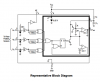
I will use MC33039 motor adapter in a design. MC33039 doesn't have a spice model. Therefore I will design internal structure of MC33039 myself. I am working the understand internal structure of MC33039. I think delay and xor gates are used to provide edge detection. Also, schmitt trigger is used for noise immunity. But I can not understand purpose of or gate and monostable. Could you explain me?
 

Attachments

  • 2.PNG
    2.PNG
    47.6 KB · Views: 152
Page 3 of the datasheet explains the operation.
 
I read datasheet many times. I built below circuit in LTSpice. At the output of or gate I take 5V, so set is 5V and reset is 0V. Since reset is 5V and reset is 0V, Q output of SR Latch is 5V. Purpose of this entegre provide speed control of motor. What are the function of or gate, nor gate and sr latch? Regards,
 

Attachments

  • sim.PNG
    sim.PNG
    119.2 KB · Views: 136
The OR gate enables any one of the three position sensors to set the latch. The NOR gate enables the lower opamp to reset the latch when (a) the OR gate output has gone low and (b) the capacitor voltage has dropped below 0.3V.
 
I understood purpose of latch. But in my simulation results are not correct. When negative and positive edges detected, I take below simulation results. When hall sensors connected to or gate, I take only 5V. Could you examine my design?
 

Attachments

  • delay 18.11.PNG
    delay 18.11.PNG
    105.6 KB · Views: 125
  • mc33039.asc
    7.7 KB · Views: 120
Can't run your sim as I don't have all the models. Here's my version (A1 etc have default values for 1V logic).
OR-NOR-SR.JPG
 
If you're interested, here's my own LTspice model for the MC33039 adapter.
 

Attachments

  • MC33039_Test.asc
    2.8 KB · Views: 134
  • MC33039g.sub
    1.4 KB · Views: 114
  • MC33039g.asy
    975 bytes · Views: 111
Status
Not open for further replies.

Latest threads

New Articles From Microcontroller Tips

Back
Top