Continue to Site

Welcome to our site!

Electro Tech is an online community (with over 170,000 members) who enjoy talking about and building electronic circuits, projects and gadgets. To participate you need to register. Registration is free. Click here to register now.

  • Welcome to our site! Electro Tech is an online community (with over 170,000 members) who enjoy talking about and building electronic circuits, projects and gadgets. To participate you need to register. Registration is free. Click here to register now.

interference between circuits

Status
Not open for further replies.

tomate

New Member
Hello,

New member here, and I have a interference problem with two circuits:

I have a control circuit ( 5 VDC 3A ) operating a irrigation system ( 24 VAC 1.2A ), both have the same 120 VAC source.

The control circuit, after the 120 VAC source has a spike protection device APC brand, after it is a power supply ( computer pc type ) with a 5 VCD 22A output which is the source for all the control circuit. The control circuit is populated meanly with TTL's, PIC, eprom, RTC, and recommended capacitors.

The irrigation circuit is integrated with water fluid solenoides ( 24 VAC 250mA each ) just one on at each moment, and water pump ( 220 VAC 11A ) to inject pressure to the pipeline.

The control circuit decide when start/stop the pressure pump ( by 5VDC 250 mA realy ) and start/stop each solenoide for watering ( by 5VDC 200 mA realy ). All relays have its protection diode, and are powered by a TTL latch with a transistor between them.

The 24 VAC source is just a transfomer 120 VAC / 24 VAC without any other devices between the transformer and the solenoide.

PROBLEM:

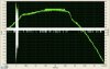
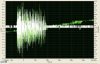
Some times that the control circuit power any relay to open the solenoide valves ( 24 VAC ), the control circuit experience a voltage fluctuation and some times a badly unexpected operation. The 5 VDC variation goes from 3.5 to 6.2 VDC, and the TTL's must be in the 4.75 - 5.25 VDC range.

QUESTION:

Exist some device that I must install between the 24VAC transformer and the solenoide valves, in order to imitate the protection diode effect in a relay powered by VDC
 
Last edited:
Is the glitch only when operating the pump, or does it happen when operating the valves?

Can you separate the AC power feed for the 5V logic supply from what feeds the 24V solenoids and pump? You should run it off a completely separate AC feed, all the way back to the main AC panel.

Can you separate the ground for the 5V logic circuit power-supply from the common side of the 24Vac power-supply that runs the valves? There should be no common connection between the 5V relay coil and the 24V load that it is switching.

Is the motor contactor an optically-isolated SSR, if not it should be?
 
Last edited:
after it is a power supply ( computer pc type ) with a 5 VCD 22A output which is the source for all the control circuit. The control circuit is populated meanly with TTL's, PIC, eprom, RTC, and recommended capacitors.
How much current is being drawn from this computer pc power supply? It is possible that it is too lightly loaded. To confirm, disconnect power to the pump and solenoids and run the circuit without them. Does the 5V rail still fluctuate when the 5V relays activate and deactivate?
 
Hello MikeMI:
The glitch happen any time the 24 VAC circuit has action, solenoides or pump
Yes, I can use a differente fase ( hot line ) from the local city electric company, but finally I have just one ground line from the electric company, and it will be common in all my electric and electronic installation inside my place.
To activate the pump, the TTL's circuit power a 5 VDC relay, which one power a 24 VAC contactor coil, which one power the 240 VAC pump ( 2 fases )
Hello Kchriste:
The power supply specification is 5 VDC 22A, and the control circuit is being drawn just 550 mA, and each relay added is 200 mA, but never are more than 3 relays powered at the same time, so the total current should be 1150 mA. I will test the fluctuation without pump and solenoides.

My place is in Mexico

Thanks
 
Last edited:
I have done yours following recomendations:

1) Control circuit ( 5VDC ) and 24VAC circuit are now powered by two different electric phases, ( but they still have the common line shared ). The results are the same.

2) With the 24VAC circuit unpowered ( off ), when the control circuit power a relay, the voltage signal is steady, without any problem, so we are sure the 5VDC power supply current capacity is correct.

How can I separate the common line from the city electric company, they only supply one. Could be this done with some special device ??

Some idea how to continue working around this ?
 
You may fix your problem with the addition of some TVS type devices. Place a 1N6285CA or equivalent across the 24VAC supply and from each side of the supply to earth ground.
 
Thanks bailey45,

Let me see if I understood this,

I need install 3 TVS devices, like the model you recommend:
one in parallel between the two 24VAC lines ( near the transformer )
a second one in parallel between the hot 24VAC line and the earth ground
a third one in parallel between the neutral 24VAC line and the earth ground

Is this correct ?
 
Just one neutral exist, and it is common for both neutrals: 24VAC and 120VAC.
I have 3 hots lines ( phases ) and 1 neutral as city electric supply, the 4 lines are concentrate in one AC panel, then I have an earth ground line from a 3 meters cooper rod and the AC panel.

How can I isolate the neutral line for each phase ?
 
If you are generating the 24VAC with a two winding transformer the output of the transformer can remain isolated and not be connected to the neatral in from the city. If this is the case disconnect the 24VAC from neutral and treat it like an isolated neutral.
 
Right, the 24VAC output ( secondary ) neutral is not connected to the main neutral from the city supply.

The 24VAC transformer has 2 lines input ( 120 VAC ) and 3 lines output, I am using the extreme two ones and left unused the central one, to power 24VAC to the solenoides, the central one is not connected

Sorry the ignorance, but a TVS device is similar to a "MOV" device ?
 
TVS Transient Voltage suppressor. A MOV (Metal Oxide varistor) is a TVS.

Also you could use a Transorb which is like a fancy zener diode.
 
Ok, I will get these TVS, so the 1N6285CA is the appropiate one ?? for 24 VAC ?

Is correct to keep unconnected the central output line from the transformer ??
 
The part may also be labeled as a 1.5KE39CA. The '39' in the part number means this part operates at 39 volts. The working voltage is 33V. Your 24VAC circuit has a 24*1.414 or 33.9 volts peak.

Panasonic ERZ-V10D390 is an equivalent MOV.

The centre tap of the transformer is OK as is.
 
Thanks, I found those TVS now in DigiKey and wait for them in a few days..

But I still have a doubt: these TVS will suppress the voltage higher than its limit ( positive and negative wave section ) but what happen with the lower wave spikes ? I mean, when normal voltage is +24VAC it could oscillate from +13vac thru +37vac, then the TVS will "cut" the 24 thru 37, but the 13 thru 24 will persist ? if it is true, then this uneliminated portion will be reflected in the control circuit that I want to isolate ?
 
Hello,

I'm attaching these snapshots of the interference problem, the white signal is 5VDC and the green one is 24VAC, one is without zoom, and the other with zomm. This happen in 125 uS....

The permanent oscillation in the 5VDC signal ( 5.03 to 5.12 ) is normal for a PC power supply ??
 

Attachments

  • interferencia_sin_zoom.jpg
    interferencia_sin_zoom.jpg
    153.5 KB · Views: 250
  • interferencia_con_zoom.jpg
    interferencia_con_zoom.jpg
    153.7 KB · Views: 275
Last edited:
The transients you are trying to eliminate are above 37 volts. The smaller spikes between 24-37 should not be causing your problem.

Without the TVS devices the solenoids and motors will generate transients which can be 100s of volts. These large spikes will be causing your problems.
 
While I receive and install the TVS's, could you help me with this :

The permanent oscillation in the 5VDC signal ( 5.03 to 5.12 ) is normal for a PC power supply ?? ( please see the graph attached above ). These oscilations are happen at a very high frecuency.

Or I need see a perfect line without or less oscilations, to know that I have a correct power supply ?
 
The noise you describe is the switching noise from the regulator and should not cause any problems. Do you have filter capacitors on your control board?
 
Yes, I have tantalium capacitors on each PCB, plus the disc capacitor near each TTL or CMOS IC, and plus electrolitic capacitors on each connector between PCB's. My control circuit is not a PCB along ( it has been growing ) , I have 6 modules interconnected, there are 3 to 10 inches between them and are interconnected with 24 AWG normal cables. All the PCB's are installed over a big playwood wall, and the solenoides are 30 to 100 feet away, but the relays that power them are in the same playwood wall.
 
Status
Not open for further replies.

Latest threads

New Articles From Microcontroller Tips

Back
Top