bigal_scorpio
Active Member
Hi to all, 
Just trying to get a project going for my sons lathe, it sounded simple when he asked me to make him a speed readout for it!
Since I already had what I believe is an ideal IC for the job, the ICM 7225 counter/display driver and some spare 7 segments and an Slotted Opto sensor which I intended to get my pulse from (the pulse would hopefully occur from a driven disk with a hole to allow the LED to Excite the Phototransistor), well that was the plan
Anyway the problem is that I can't understand how to interface the pulse and the ICM7225 IC, even though it says in the Datasheet that one of its uses is a Tachometer, it fails to give even the most basic of examples that I could build on, and I'm no Einstein so stuck!
The LED side of the circuit isn't a problem to me, just the interface from pulses to RPM circuit.
If anyone knows how to do this I would be very grateful and would be able to get my project off the ground, and onto the bench! hehehe
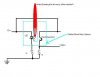
I have included my (pretty poor) but functional drawing of the optocoupler circuit which seems to work ok, though I don't have any experience of the speed these are capable of working at or if I should have one single hole or multiples?
Also I have posted the 7225 datasheet, I just hope someone will take pity on me and can help.
Thanks for taking the time to read this post...............Al
Just trying to get a project going for my sons lathe, it sounded simple when he asked me to make him a speed readout for it!
Since I already had what I believe is an ideal IC for the job, the ICM 7225 counter/display driver and some spare 7 segments and an Slotted Opto sensor which I intended to get my pulse from (the pulse would hopefully occur from a driven disk with a hole to allow the LED to Excite the Phototransistor), well that was the plan
Anyway the problem is that I can't understand how to interface the pulse and the ICM7225 IC, even though it says in the Datasheet that one of its uses is a Tachometer, it fails to give even the most basic of examples that I could build on, and I'm no Einstein so stuck!
The LED side of the circuit isn't a problem to me, just the interface from pulses to RPM circuit.
If anyone knows how to do this I would be very grateful and would be able to get my project off the ground, and onto the bench! hehehe
I have included my (pretty poor) but functional drawing of the optocoupler circuit which seems to work ok, though I don't have any experience of the speed these are capable of working at or if I should have one single hole or multiples?
Also I have posted the 7225 datasheet, I just hope someone will take pity on me and can help.
Thanks for taking the time to read this post...............Al