Andrew Leigh
Member
Hi,
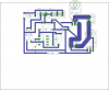
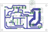
I now have my 12V thermosat schematic ready for board design. While thinking about the PCB I got to thinking about the track width. I expect to be switching about 16A through a Mosfet. How does one interface the high current carrying leads with the PCB. I was hoping to use PTR Connectors AK500/2 and /3.
What confuses me is the following;
- theortically I need about 6,5mm², (from wire tables) this translates to a track width of ~ 162mm?
- Why if I need 6.5mm² are the legs on the Mosfet barely 1mm².
Evidently I am missing something here, could someone point me in the right direction?
Cheers
Andrew