Continue to Site

Welcome to our site!

Electro Tech is an online community (with over 170,000 members) who enjoy talking about and building electronic circuits, projects and gadgets. To participate you need to register. Registration is free. Click here to register now.

  • Welcome to our site! Electro Tech is an online community (with over 170,000 members) who enjoy talking about and building electronic circuits, projects and gadgets. To participate you need to register. Registration is free. Click here to register now.

INSIGNIA LCD HDTV help

Status
Not open for further replies.
Well, somehow my dad got ahold of a broken HDTV from a friend that would have ended up in a dumpster, and I have been asked to attempt to repair it.

While figeting with the power button to try and see if it was just the lamp that went out with a flashlight I was able to get it to turn on once. From there, it seemed as if everything was fine. I tested most of the video/audio inputs and it seemed as if nothing was wrong

Finally came the point to turn if off and see if it would come on again......it didn't

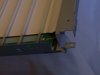
Because of how irratic it was being, I've tested and fixed a few cold solder points on the main board, the board with all of the input switches on it, and the board that has the green power light/IR receiver. This didn't change anything. I have yet to test the internal power supply and one more board attached to the actual LCD screen for cold solder points.

In the case that more cold solder points aren't the problem, what are some common components that go out in these and where would the general area be to find them?


the thing did come from a bar, so it was mostlikely on almost 24-7
 
When it doesn't come on are you sure it's not just the backlight? You can sometimes tell by looking very closely at the screen you'll see the image change slightly. That's if it's actually an LCD not a plasma.
 
When it doesn't come on are you sure it's not just the backlight? You can sometimes tell by looking very closely at the screen you'll see the image change slightly. That's if it's actually an LCD not a plasma.

I"m not absolutely positive, but I did try to find an image on the screen holding it at angles and using a flashlight.
 
Be sure, it changes the way you approach the problem completly.
 
Usually, if the backlight has a problem, the set will flash an error indication on the LED, and shut the set down totally - so it's rare to be able to see a picture at all with no backlight.

Some cheap and nasty portables by allow you to see the picture though.
 
Last edited:
While checking the Lamp's driver board for cold solder points, I did notice a surface mount LED attached to it, but it doesn't turn on when the board is on.

I tried looking at it again, but there isn't even a faint change in the screen, so I'm beginning to think that it can't be the fluorescent tube.

since it was given to us, I was able to get it to turn on once, but that was after figeting with the power button while trying to find a faint image on the screen.

is there any component that may cause the set to behave this way? I was thinking maybe a capacitor somewhere in the thing, but seeing as it is only about 2-3 years old I don't see how it could be this.
 
freak, what Nigel is saying is that if the backlight isn't working the unit won't be allowed to power on. Intermittent function of the unit could mean so many things it's hard to track down. Also define 'playing' with the power button? Are you sure there isn't just something wrong with it, or the power on circuitry?
 
By that I mean pressing the power button until the green power light comes on in the front, and then a few seconds later pressing the power button until the power on light goes out. waiting afew more seconds, then turning it on again. Even leaving it with the power light on for 10min doesn't give any image on the screen.


I haven't checked the power supply yet, but it will be done tonight as soon as I have someone to spot me while discharging its capacitors.
 
Well, I just looked over the power supply and LCD driver and there wasn't anything out of the ordinary.
I was thinking, if I unplug the two leads that run to the backlight then power the thing on and it still acts the same, would it be a broken/burned backlight?

I don't know what else to try.
 
Well, I just looked over the power supply and LCD driver and there wasn't anything out of the ordinary.
I was thinking, if I unplug the two leads that run to the backlight then power the thing on and it still acts the same, would it be a broken/burned backlight?

No, like I said before, sets won't work if the backlight isn't running - even a single tube not working will stop it entirely.

However, I would suggest a duff tube is one of the most unlikely possibilies.

First off, particularly for a cheap nasty set like this, you should check all electrolytics in the PSU using an ESR meter.
 
I've tested most of the electrolytic capacitors on the power supply using my multimeter--it has a capacitance test built in. The only one that it wouldn't read is the giant filter capacitor, which it's written value exceeds what the meter can measure.

Sorry, but what is a duff tube?


Also, I've never worked on anything with flourescent tubes before, but is there anything that I can put in place of the tubes and trick the set to allow it to give an image such as a short or a resistor?
 
^^sorry, a somewhat stupid question,

Is there any visual inspection that might show a dead tube

also, I just dissassembled the tube housing and found what looks like a cold solder joint on one of the lines that supplies the High voltage. I'm hoping that's it.

Also, among the tubes, there is one that is slightly darker than the rest. Could this be a dead tube? if so, could I possibly replace it with a very thick wire to test the rest of them and see if it is the problem with the unit? (it is the lowest one in the first pic and the furthest right one in the second pic)
 

Attachments

  • 100_2670.JPG
    100_2670.JPG
    748.2 KB · Views: 452
  • 100_2672.JPG
    100_2672.JPG
    785.1 KB · Views: 737
Last edited:
I've tested most of the electrolytic capacitors on the power supply using my multimeter--it has a capacitance test built in. The only one that it wouldn't read is the giant filter capacitor, which it's written value exceeds what the meter can measure.

You can't check them with a multimeter, or a capacitance meter, you MUST use an ESR meter - low ESR is by FAR the most common fault, and is what causes problems.

Sorry, but what is a duff tube?

The backlight tubes, CCFL's.

Also, I've never worked on anything with flourescent tubes before, but is there anything that I can put in place of the tubes and trick the set to allow it to give an image such as a short or a resistor?

No, there's usually a complex feedback arrangement which sums the outputs from all the tubes together.
 
Well, that cold solder joint wasn't the main problem, although I am a little confused on how the thing even turned on before if there was no current running to the screen

Because I don't have an ESR meter, and the price on a few from the net seem a bit daunting just for a tv that will most likely fail again, I think I'm gonna put this one aside and return to a few other projects.


thankyouguys for all of your help.
 
Well, that cold solder joint wasn't the main problem, although I am a little confused on how the thing even turned on before if there was no current running to the screen

Because I don't have an ESR meter, and the price on a few from the net seem a bit daunting just for a tv that will most likely fail again, I think I'm gonna put this one aside and return to a few other projects.

If you have a scope, then check for ripple on the electrolytics, but obviously the set has to be powered and the PSU running to do this.
 
I do not have a scope. I almost bought one, but then later found out that my college has a lot of that equipment already.

What were probably gonna do is take it to someone who most likely already has the proper tools to check this thing, tell him/her what we've found out, and see if we can have him/her just look for what part is broken (to try and keep the repair as cheap as possible). I can then just replace the broken component (depending on if they are willing to do that or not)
 
what u need to do is disconnect the invertor from the power supply,then switch the set on and check to see if yr 24v rail for the invertor is present,check the standby 12v,and 5v rails,there may also be a 3.3v rail too used by the micro on the signal panel-with the set in standby with the invertor disconnected there should also be some supplies that are always present-5v supply being one of them.
if you get no voltages from the secondary of yr power supply it could mean you have a simple powersupply fault on the primary side of the supply stopping it from starting-low esr electrolytics,start up resistors high in value or oc-depending on model there are many powersupply kits available which will cure most psu problems.the other thing to check is the power on signal from the signal panel-may be active hi or lo depending on model if this is missing the supply wont come on.
the fact the invertor initially worked ruled out a fault with the lcd backlight assy-you shouldnt have dissassembled it as they are made in clean room conditions and any dust ,dirty fingerprints etc will be visible on switch on when the lcd is working.
another item on the invertor board to check is each individual transformer,you only need one to fail which will shut the set down. be very careful with taking measurements in this set and if using a scope you need an isolation transformer to power the set or you will cause more problems -if you need a service manual then let me know and i can supply one for it
mike
 
where i work we see a lot of TV's including insignias. the most common problem with them is bad caps in the power supply. the second most common problem is bad inverter boards (the ones that feed the FL tubes). the inverter boards have a sense circuit that will tell the main cpu that the inverter isn't working. you might try removing the dark FL tube and see if it then lights up. i've found that an ESR meter pays for itself very quickly. if you have a function generator you can make an ESR tester jig. feed the function generator (100khz sine wave10V p-p) through a known resistor to a set of test probes. read the voltage across the probes with an oscope or a true RMS DMM. with a cap connected across the probes, the voltage is proportional to the capacitive reactance (which at 100khz should be pretty low)at 100Khz plus the ESR.
 
faulty electrolytics seem to appear all the time with lcd power supplies-there is one particular phillips type which for the standby 5v supply has 1000mf at 10v fitted-which is fine-but on the 12v switched supply also you find 1000mf 10v fitted-of course over time they split and start leaking which can give anything from a set that takes 30 mins to switch on,10 mins to respond to a remote control command or a set that point blank refuses to switch out of standby....it makes you think who is designing these power supplies because they arent doing a very good job of it so far by what ive seen.........
 
Last edited:
they should have "stupid design of the year" awards for engineers......, and then have "stupid parts substitution of the year" awards for the bean counters that decide " a 10V cap is $0.02 cheaper than the 16V one, so use the 10V one instead". not to mention that they use the cheapest caps on the planet which fail for no reason.
 
Status
Not open for further replies.

Latest threads

New Articles From Microcontroller Tips

Back
Top