Continue to Site

Welcome to our site!

Electro Tech is an online community (with over 170,000 members) who enjoy talking about and building electronic circuits, projects and gadgets. To participate you need to register. Registration is free. Click here to register now.

  • Welcome to our site! Electro Tech is an online community (with over 170,000 members) who enjoy talking about and building electronic circuits, projects and gadgets. To participate you need to register. Registration is free. Click here to register now.

Inrush NTC must handle 32kW peak power waveform.....will it be damaged?

Status
Not open for further replies.
Hi,
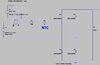
We are using the B57234S0509M NTC.
Its for inrush into a 190-265VAC offline flyback SMPS with an input electrolytic capacitor of 150uF.
The schem and inrush power waveform is as attached (this is with mains applied at mains peak and when VAC = 265VAC. (Also, LTspice schem is as attached).
Do you think this NTC can handle this ….how many times?
The datasheet gives no indication of i^2.t or allowable power vs time waveforms.

The 3R inrush NTC energy is 16Joules, and this is over 500us. Datasheet doesn't verify this.

If ambient is 40degc at the time of switch ON, then there is a 33kW peak power pulse (as shown). I strongly doubt that this little NTC can handle this without some damage?

B57234S0509M NTC datasheet
 

Attachments

  • INRUSH NTC 3R _Power Waveform.jpg
    INRUSH NTC 3R _Power Waveform.jpg
    61.8 KB · Views: 197
  • INRUSH NTC 5R _Power Waveform.jpg
    INRUSH NTC 5R _Power Waveform.jpg
    54.5 KB · Views: 186
  • INRUSH NTC Schem.jpg
    INRUSH NTC Schem.jpg
    50.9 KB · Views: 187
  • INRUSH NTC 3R.asc
    2 KB · Views: 173
While I don't use a lot of these devices, I do notice they give a "discharge" maximum C of 700uF across a 1 ohm load resistor at 230V, so your 150uF should be ok, assuming your initial load has at least 1 ohm internal resistance (page 15). Discharge and/or charge should be similar. Remember that Imax is 6.4A. Also, the 5 ohm resistance at 25C is just that, at around an ambient 40C, the resistance drops to around 3 ohms to start with.
Keep an eye on Pmax of 3.6W at 25C.
The Imax of 6.4A is only good to 65C. Higher temps require the current to be less (see their derating calculations in datasheet). You have to determine the final load current.
Most devices are rated for "average" for things like current, or some give ratings for one cycle at 60Hz (or 50Hz). As long as you don't exceed those ratings, you should be ok.
 
Thanks, that test at page 15 doesnt look relevant to us, as there is the 1 ohm of series resistance, which doesnt appear in the real circuit in our case.

Its an "Inrush NTC, " and im amazed the datasheet doesnt just give an example of an inrush event, as it happens in a PSU that suddenly gets connected to the power source.
 
Well, consider that the inductor and the diode will provide some "resistance" to the AC voltage in the first surge. It may work out to be close to 1 ohm for the first cycle, but that is a wild guess....
 
The whole idea of an inrush NTC is to limit the current. That's what they do, and they do it very well. That data sheet is 15 years old, and EPCOS wouldn't still sell them if they didn't work. I have used a few, on the input to transformers where the transformer can saturate on turn-on and be virtually a short for 1/4 cycle.

A 150 μF capacitor charged at the peak of mains voltage will contain about 10 J of energy. If it's charged from the peak mains voltage, via a resistor, the heat energy in the resistor will be about the same as the energy in the capacitor.

The NTC has a thermal capacity of 1530 mJ/K, so the 10 J of energy will raise its temperature by about 15 °C or °K, or about 28 °F. That seems fine to me.

The in the test with the 700 μF capacitor, the 1 Ohm resistor is probably there to stop the current getting excessive once the thermistor has warmed up. There is about 5 times the energy in the 700 μF than in a 150 μF, and just about all of that energy will end up in the thermistor, so I don't think you will have a problem with the 150 μF inrush.
 
Thanks, but do you think the thermistor can physically rise up by 15 degc in 500us?...surely it will cause a stress crack?
A sine wave AC input is not instantaneous. At 60Hz, the one "side" of neutral takes 8.3ms to rise and fall. It starts at zero volts (depending on when you switch it on of course) and rises to maximum in about 4.15mS. Current is low at first as the voltage is low, and rises as the voltage rises.
Now, if you switch on near a peak, yes, there will be more current at first, but that is why one could use a zero crossing detector to switch on the power only at the zero voltage mark, if concerned about current surges.
A thermistor will not rise 15C in a short period, as energy in 500uS will be minimal when averaged over time of the AC waveform. Try your modelling with different AC input - start at zero volts of the AC cycle. You seem to be modelling with a peak start only.
The whole idea of an NTC inrush limiter is to reduce the current surge when turning on near the peak of the supply. An alternative would be to turn on near zero. If that is done, there's no need to have an NTC limiter. However most power supplies don't have any active components before the rectifier and capacitor, so a circuit to wait for zero volts would be quite complicated.

If the turn-on is near the peak voltage. the 15 °C rise will be very quick. The time constant will a bit under 1 ms, so the heating of the thermistor will happen in about that time. The NTC will reduce the damage to the switch, fuse and capacitor, which is why it's fitted.

This application is using the NTC exactly as it is intended to be used, so it'll work fine.

It is much more difficult to work out the heating when the capacitor has charged.
 
This application is using the NTC exactly as it is intended to be used, so it'll work fine.
Thanks, i agree, but then, if thats the case, why is it we can't use a smaller, cheaper NTC of say 10mm diameter, or even 7.5mm diameter.
I mean, as long as it can handle the RMS current level.
At some point, there's some way of calculating that for 265vac mains and at_peak switch on, and with a 150uF capacitor, such-and-such a size NTC is the one.
Our RMS current by the way is just 0.8Arms.
 
Status
Not open for further replies.

Latest threads

New Articles From Microcontroller Tips

Back
Top