jonschorah
New Member
can anyone help here please?
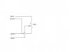
i am using several of the below to reduce the level of some audio signals i'm recording through my soundcard.
i would like to add an LED to the circuit to register an input signal, but i don't want it to affect the audio signal level by drawing off current.
at the moment i have 8 volume controls like the diagram and would like to add an LED to each and run the whole lot off a 9v battery.
(sorry if the diagram is wrong, it's supposed to represent a couple of mono jack plugs wired up to a potentiometer)
")
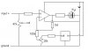
") . i can get those componets through the uk version of the site you mention (farnellinone)
. i can get those componets through the uk version of the site you mention (farnellinone)