Continue to Site

Welcome to our site!

Electro Tech is an online community (with over 170,000 members) who enjoy talking about and building electronic circuits, projects and gadgets. To participate you need to register. Registration is free. Click here to register now.

  • Welcome to our site! Electro Tech is an online community (with over 170,000 members) who enjoy talking about and building electronic circuits, projects and gadgets. To participate you need to register. Registration is free. Click here to register now.

Input protection

Status
Not open for further replies.

andy257

Member
Hi all,

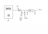
Building a small uC board which is going to be used in a noisy industrial environment. I want to try and give my circuit some protection from possible spikes / emc interference. The board uses a 7805 regulator with decoupling caps and takes its power from a 12V switch mode power supply.

I was thinking of using a fuse and dummy diode and maybe a tranzorb on the input stage.

Do you think its necessary to add any additional filtering to the board. I assume most switch mode power supplies are reasonably clean and most of them seem to have good protection/safety features themselves

If anyone can provide some tips or experiences they have had with circuit protection i would love to hear from you.

thanks
 
Last edited:
What's a "dummy diode"?
 
Crutschow - a diode to prevent incorrect polairty. Forgive me if you are joking.

blueroom - the board does a mix of both. Measures temperature, controls pwm fans, switches relays, rs232 comms etc.

I just thought the power section could do with some input protection. Like i say, the SMPSU is an off the shelf type, has protection of its own, but its not to say a fault wont pass through to other devices its powering.
 

Attachments

  • input protection.jpg
    input protection.jpg
    9.1 KB · Views: 221
Last edited:
The diode is fine, transorb probably not necessary. How much current does your circuit draw? At 12V those 7805's will need a heatsink even for light loads.
 
Last edited:
Do you know what a crowbar circuit is? For this, a 13 or 15 volt zener to the gate of an SCR, put this where the tranzorb is so it will blow the fuse if the smps goes high.
 
The diode is fine, transorb probably not necessary. How much current does your circuit draw? At 12V those 7805's will need a heatsink even for light loads.

yes i was also wondering if the tranzorb was necessary. I have not included a heatsink as of yet, i was hoping to avoid if possible to reduce the profile of the board. Ive gone for a smt type 7805 (DPAK) and made the rear face pad (GND) as large as possible. I have not done any current measurements yet but i would say 0.5A max.
 
Crutschow - a diode to prevent incorrect polairty. Forgive me if you are joking.
No, I was serious. I just wasn't familiar with the term. Reverse polarity protection diode I understand.
 
I have not included a heatsink as of yet, i was hoping to avoid if possible to reduce the profile of the board. Ive gone for a smt type 7805 (DPAK) and made the rear face pad (GND) as large as possible. I have not done any current measurements yet but i would say 0.5A max.
As Bill noted, you would need a heatsink or go with switchmode supply for that load current. The 7805 power would be (12-5)V x 0.5A = 3.5W with a 0.5A load, which is more than the PC board alone can likely dissipate.
 
What is the maximum power a 7805 can dissipate without a heatsink?
 
I would also make sure the analog and digital inputs are adequately protected not that you haven't already. Resistors and fast clamp diodes protect from most spikes.

0.5A in a 7805 sounds like a bit too much without a heatsink especially if you are dealing with the full industrial temp range.
What is drawing so much current and for how long? if you have very very low duty cycle you might be able to get away with
not using a sink.

Or, possibly some of the higher current stuff(solenoids,etc) can run directly off 12v?
 
Last edited:
What is the maximum power a 7805 can dissipate without a heatsink?
Depends upon the package type.

Edit: See this for the thermal resistance to air of some typical packages along with a calculator to determine the maximum power dissipation for a given ambient.
 
Last edited:
The most you could expect out of the DPAK is about a watt. If you check the data sheet the junction rise over ambient is 95C per watt with a maximum junction temperature of 125C. So with your 7 volt drop across the regulator you could only expect .14 amps. The PC board will help but it is not the best heat sink (one side is insulated and the copper is to thin to dissipate the heat well). About all you can expect from the board is about 50C per watt. The better choice, if you stick with the linear regulator, might be the TO 220 and a small heat sink. You need to get rid of 3.5 watts (7v x .5a). You can get a rough estimate of the heat sink size using Trise=50/sq rt of the area in cm. A little aluminum U shaped heat sink with a couple of square inches would do it.
 
i would replace diode and transorb by a unidirectional TVS ike this one (same as zener but a lot more fast and can take high current transient), it can absord very high surge and it is also act as a regular diode
**broken link removed**
 
Here's a good way to protect circuits from spikes.

It's a TRANSIL diode manufactured by ST. It's available uni- and bidirectional for a great range of voltages.

I use it for protection in automotive applications and it has never failed till now.

Have a look at the data sheet.

The correct schematic symbol (DIN) is also attached.

Boncuk
 

Attachments

  • 1,5KExxCA.pdf
    76.3 KB · Views: 266
  • TRANSIL.gif
    TRANSIL.gif
    4.8 KB · Views: 352
I have looked at those TRANSIL diodes. I spent some time on ST's site after ordering one of their Discovery 32 uC starters.

I have a few up-coming automotive projects for clients, and I typically use TVS diodes.

These TRANSILs have very fast reaction times, and and offer very high protection.

Boncuk said:
I use it for protection in automotive applications and it has never failed till now.
What caused it to finally fail? Or were you saying that it hasn't failed yet?
 
Status
Not open for further replies.

Latest threads

New Articles From Microcontroller Tips

Back
Top