Continue to Site

Welcome to our site!

Electro Tech is an online community (with over 170,000 members) who enjoy talking about and building electronic circuits, projects and gadgets. To participate you need to register. Registration is free. Click here to register now.

  • Welcome to our site! Electro Tech is an online community (with over 170,000 members) who enjoy talking about and building electronic circuits, projects and gadgets. To participate you need to register. Registration is free. Click here to register now.

Input impedance darlington tor

Status
Not open for further replies.

SneaKSz

Member
Hello all,

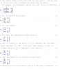
I was reading an audio amplifier book (by bob cordell) and he said the β8=100 and β10=50, the collector of Q4 would see 100*50*8=40kΩ.

I understand that this would be the case if R11 wouldn't be included and R13 is low and left behind, but R11 infects the input impedance.

Why can the input impedance be calculated by using the formula above?
Doesnt Q9 and Q11 also being active, not infect the collector impedance of Q4?

And finally shouldn't Q5 also be taken into account when determining the collector impedance of Q4?
**broken link removed**
These are some questions I've been banging my head over lately.

Hopefully you guys can point me out in the right direction!

kind regards !
 
Last edited:
Well I use a small-signal mode to find the input impedance for Q8 Q9 and R11, R13, RL

[LATEX]Rin = \frac{(\beta 1 +1)(\beta 2+1)((R13 RL+R11 (R13+RL))}{R11+ R13(\beta 2+1)} = 28.688K\Omega[/LATEX]

Where β1 = Q8 and β2 = Q10.

And we don't need to include Q9 and Q11 and Q5 in our model. Error introduced by Q9,Q11,Q5 is practically negligible.
 
Last edited:
Hello jony, thanks for the answer!
Are you able to scan calculations you made to retrieve Rin?
Could you tell me why Q5 is neglected?

Here are my calculations, also with the PI model.

View attachment 67290

Kind regards!
 
Last edited:
Hi, today I use Mathematica software and Jacob Shekel circuit analysis method to find Zin.
This method is described by The Electrician in this thread
https://forum.allaboutcircuits.com/showthread.php?p=165051#post165051
https://forum.allaboutcircuits.com/showthread.php?p=289293#post289293

So the full equation for Zin of a Q8 and Q10 look like this

[LATEX]Zin = \frac{(1+\text{$\beta $1}) ((\text{R13}+\text{re2}) (\text{re1}+\text{RL}) (1+\text{$\beta $2})+\text{R11} (\text{R13}+\text{re1}+\text{re2}+\text{RL}+(\text{R13}+\text{re2}+\text{RL}) \text{$\beta $2}))}{\text{R11}+(\text{R13}+\text{re2}) (1+\text{$\beta $2})} = 23.660K\Omega [/LATEX]

I assume β1 = 100; β2 = 50 and Ic8 = 20mA ; Ic10 = 0.1A and re = 26mV/Ic

And if we assume re1 and re2 = 0 we get the same equation that I post in previous post.

So Zin seen by Q4 collector is equal

Zin = 23.6K ||ZoQ7 ≈ 23.6KΩ


[LATEX]ZoQ7 = \frac{\text{R10} (\text{re1} \text{ro}+\text{R9} (\text{re1}+\text{ro})) (1+\text{$\beta $1})+\text{R10} \text{R9} \text{ro} \text{$\beta $1} \text{$\beta $2}+(\text{re1} \text{re2} \text{ro} (1+\text{$\beta $1})+\text{R9} (\text{re2} \text{ro}+\text{re1} (\text{re2}+\text{ro}) (1+\text{$\beta $1}))) (1+\text{$\beta $2})}{\text{R10} (\text{R9}+\text{re1}) (1+\text{$\beta $1})+\text{re1} \text{re2} (1+\text{$\beta $1}) (1+\text{$\beta $2})+\text{R9} (\text{re1}+\text{re2}+\text{re1} \text{$\beta $1}+\text{re2} \text{$\beta $2})} [/LATEX]

But if we assume re1 = re2 = 0Ω then

[LATEX]ZoQ7 = \text{ro}+\frac{\text{ro} \text{$\beta $1} \text{$\beta $2}}{1+\text{$\beta $1}}[/LATEX]

So if ro = 10K , β1 = β2 = 100 then ZoQ7 = 1MΩ (700KΩ is we use a full equation)
 
Last edited:
Hello,
great method to find the impedances and gains! With the attachments by the electrician, I understand how you created the matrix and got the Zin.

I manually determined the Zin for the darlington ( without re') and finally got the same equation.

Are you able to send me the pdf for the Zout of the current source?

I have 1 thing I dont understand about the active matrix. If I would have a bjt with collector and emittor a resistance, I have a 3*3 matrix ( standard). But when the collector is grounded ( darlington example), the row for the collector is deleted. Should there be 2 collums of zero's?

And if the emittor is connected to gnd, than only (1,1) and (1,3) of the standard bjt matrix stay..

Try to search in the posts of 'The Electrician' but didnt really got it.

thanks for the great help!
 
Last edited:
Are you able to send me the pdf for the Zout of the current source?
Sure I can.

I have 1 thing I dont understand about the active matrix. If I would have a bjt with collector and emittor a resistance, I have a 3*3 matrix ( standard). But when the collector is grounded ( darlington example), the row for the collector is deleted. Should there be 2 collums of zero's?

And if the emittor is connected to gnd, than only (1,1) and (1,3) of the standard bjt matrix stay..
I'm not quite understand your question. But if we want to included ro then simply connect resistor between collector and emitter.
 
Last edited:
Thanks for the help Jony!

well I'll try to explain my question a little bit more precize.

In this link : https://forum.allaboutcircuits.com/showthread.php?t=26710&page=6.

Here, you tried to analyse the circuit with this special method, you have a different array for Q2 when compared to the standard ( 3*3) BJT array. I thinks this is because the emittor is connected to the ground. (https://forum.allaboutcircuits.com/attachment.php?attachmentid=11669&d=1250886068).

And also what should be done to the standard BJT matrix (3*3) if the collector was grounded? This was done in the darlington configuration, but I dont really get why the active array is formed like that.


e.g. in the current source example, the array for Q1 is formed in a different way than usual. View attachment 67362
Hopefully you understand my question(s) a little bit better!

Kind regards
 
Last edited:
Ok, thanks I got this now.

And what about the positioning in the matrix? This is from the current source, why is it array 1 that's correct and not array 2?

kind regards!
 
Last edited:
Thanks, now I've got how you guys got those arrays.

Thank you very much Jony, for learning me this method! Could this also be applied to fets?

kind regards
 
Could this also be applied to fets?
I don't know, but probably you can but I I've never tried. I only use it for BJT and op amps.
Maybe The Electrician can show as some light on this.


Tried the Vbe multiplier's output resistance

View attachment 67373View attachment 67374View attachment 67372

Does this sound allright?

I reworked the Zout than so it would be clear that the output resistance is really low. Instead of the tor the Calculated Zout can be connected to node 1 and 3, so it could be incorporated for the Zin of the darlington right?
As for Vbe multiplier output resistance. Your matrix looks god but you forgot to short one of a nodes ( GND is missing). See the pdf file.

Also you shoudl kept in mind that we can ignore Q5 because his low impedance ZoutQ5 ≈ 20Ω.
As for Q9 and Q11. If we assume that the bias current is equal 0.1A, then for the low output signals. When output stage work in class A. The impedance seen by Q4 collector is almost the same as for the class B ( Q9 and Q11 are in Cutt-off or Q8 and Q10). The circuit work in class B if IL > 2*bias current = 0.2A. And this give Vload = 0.2 * 8Ω = 1.6V.
 
As for Vbe multiplier output resistance. Your matrix looks god but you forgot to short one of a nodes ( GND is missing). See the pdf file.

I didnt know if I had to short the collector yes or no. That because the source is a current source. So I should also ground it when the supply is a current source?
 
But if you are measure resistance you measure it between two terminals, you don't measure open circuit resistance. So you need a reference node (GND).
 
Last edited:
Yea youre right, my fault. But what should normally be grounded than? The collector or emittor of Q5. The collector of Q4 is creating an AC signal, so then its more like finding the input impedance of Q5 and that would mean that the collector of Q5 is grounded and the input signal is attached to the emittor of Q4. Now we have two terminals to measure the input impedance.

Does this sound right?
 
It doesn't matter which of the two terminals (emitter or collector) you chose as a reference point. The impedance will be the same.
 
Thanks, now I've got how you guys got those arrays.

Thank you very much Jony, for learning me this method! Could this also be applied to fets?

kind regards

Yes, it can be used with FETs; see the attachment.
 

Attachments

  • Shekel Question.png
    Shekel Question.png
    16 KB · Views: 336
Status
Not open for further replies.

Latest threads

New Articles From Microcontroller Tips

Back
Top