Hi,
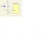
Normally,our project toy whose Ic input I/O port have 5-50ms debounce time.Those IC have put down capacitor 0.1uF and resistor 1Mohm!
My question is: whether I can cancel capacitor 0.1uF and resistor 1Mohm in order to save money. If I cancel them that mean those Input I/O port is floating,what will influence toy electronic function? Do it happen abnormal.