Continue to Site

Welcome to our site!

Electro Tech is an online community (with over 170,000 members) who enjoy talking about and building electronic circuits, projects and gadgets. To participate you need to register. Registration is free. Click here to register now.

  • Welcome to our site! Electro Tech is an online community (with over 170,000 members) who enjoy talking about and building electronic circuits, projects and gadgets. To participate you need to register. Registration is free. Click here to register now.

Infrared Remote Control - corrections?

Status
Not open for further replies.

Menticol

Active Member
Hello!

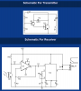
I've found this simple circuit on the net, It's an single channel IR remote control. I hope somebody could find it useful.

The only problem is, I got it from a site with bad reputation of non working schematics - It's pablin.com.ar, to avoid copyright issues.

Should I correct something, before starting etching?

Emmiter
**broken link removed**

Receiver
**broken link removed**

(Receiver needs +9v -9v to work)

Thank you in advance
 
It is the same defective very old circuit at Aaron's Homepage .
The LM308 opamp has not been made for about 13 years.
It is missing a 100k to 1M resistor from its pin 3 to 0V for its 0V reference voltage.
The author didn't know that the -9V battery can be replaced by a couple of resistors.
 

Attachments

  • defective infrared remote control.PNG
    defective infrared remote control.PNG
    17.4 KB · Views: 416
Damn! I just got the Lm308 today, 13 years old? Now I know why I had to pay a lot for it!!! :mad:

Please Audioguru, is the 100 ohm resistor (I have chosen it randomly between 100K and 1M) between pin 3 and GND, enough to avoid the using of -9V on pin 4? or where should the pin 4 be connected?

The datasheet doesn't give me any help.

Thank you in advance, and sorry by the nuisance
 
Last edited:
The added 100k to 1M resistor (not 100 ohms) makes pin 3 input of the opamp at 0VDC when the opamp has a positive and negative supply. If the opamp has only a single positive supply then pin 3 must be biased at half the supply voltage with two resistors.
 
Thank you so much Audioguru, you saved my day again!

Is this the correct way to biasing pin 3?


**broken link removed**

I made the calculation as follows

Power consumption of the circuit: 300 mA
Supply voltage: 9V
R = 4,5 / 0,300 = 15 ohm

One last question: If my procedure is correct, can I feed the circuit with only 5V? My project will run with 12V, the LM308 can handle up to 18, but LM567 just can handle 9... and I have a 7805 at hand

Recalculating R1 again offcourse
 
Last edited:
No.
Pin 3 is the input of the LM308. Its current is almost nothing, certainly not 300mA. The entire circuit draws about 10mA plus the current for the relay. The pin 3 input current of the opamp is only 0.0000000015A (1.5nA).

Your 15 ohm resistor is shorting the output signal from the photo-transistor and is shorting the input of the opamp to the positive supply where it does not work.

Pin 4 must be connected to 0V then pin 3 has a 1M (one million ohms) to ground and another 1M to the positive supply. Then pin 3 will be at half the supply voltage.
 
It doesn't work. When I adjust the Potenciometer, the relay activates only when I reach the end of it, and ignores the emmiter. At some point of the potenciometer scale one of the IC's starts making a high frecuency noise

tested with 2 pin and 3 pin IR receiver

Don't know what to do...
 
Last edited:
The circuit is supposed to use a photo-transistor. It will not work with a photo-diode and it won't work with an IR receiver.
If the pins on the photo-transistor are backwards then the circuit will not work.
If the photo-transistor is in light then it probably will not work.
 
Last edited:
Status
Not open for further replies.

Latest threads

New Articles From Microcontroller Tips

Back
Top