Continue to Site

Welcome to our site!

Electro Tech is an online community (with over 170,000 members) who enjoy talking about and building electronic circuits, projects and gadgets. To participate you need to register. Registration is free. Click here to register now.

  • Welcome to our site! Electro Tech is an online community (with over 170,000 members) who enjoy talking about and building electronic circuits, projects and gadgets. To participate you need to register. Registration is free. Click here to register now.

Inductance Problems

Status
Not open for further replies.

Sceptre

New Member
hey guys,

i have a circuit setup, which is just a big magnet that is switched on and off using a MOSFET and a TTL signal. My problem is, due to the high inductance (~2400H) I am burning out my mosfet. What is a reliable way to stop this? Diode across the mosfet?

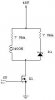
Here's a quick and dirty circuit schematic :D
The resistor and the inductor simulate the magnet and the resistor and diode in parallel makes sure i get clean magnet pulses when i shut off the magnet.
 

Attachments

  • circuit_131.jpg
    circuit_131.jpg
    4.6 KB · Views: 692
I posted a similar circuit recently for controlling a motor. But you are correct, I would place another diode with its anode to the source and cathode to the drain of your mosfet.
 
crust said:
I posted a similar circuit recently for controlling a motor. But you are correct, I would place another diode with its anode to the source and cathode to the drain of your mosfet.

i dont' have any regular diodes around with the rating I need....can I use a schottky diode in the manner you suggested?
 
Definately put a diode across FET.. but you know what, you might have one already built into the FET(which is the case many times for most Power FETS).. If that is the case, you may be operating outside of FETS SOA curve.. If you tell me what the FET part # is, I can check it against your circuit to see if I can spot a spec violation.
 
solution for MOSFET problem.

try use this triac TIC226M
do not use MOSFET coz it is for drive low current circuit....otherwise u also try use power transistor.
 
I agree, there may be a diode built into the power mosfet. Earlier, when I saw the circuit I assumed that the poster was using a "logic compatible" MOSFET since they are driving it with a 5V signal. If it is a regular mosfet, it will probably not go fully into its enhancement mode (though in that case the drain-source current would be low).
 
Your peak flyback voltage will be twice your supply voltage, so unless you have a 100 volt MOSFET, it may break down. Here's how it works: When the magnet is fully charged, it has about 7 amps (48v/7 ohms) flowing through it. When you turn off the MOSFET, that current cannot decay abruptly. The voltage at the drain jumps abruptly to 48(+) volts, causing D1 to conduct. The full 7 amps is initially flowing through D1 and the series resistor, so the peak voltage at the drain is 48v + the diode forward drop + the drop across the resistor (7 ohms*7 amps), for a total of around 97 volts. You can reduce the flyback voltage by decreasing the value of the resistor in series with the diode D1. Try 1 ohm instead of 7 ohms.
You can put a diode across the MOSFET, but I don't see any way you are going to get a negative transient on the drain, so I don't think it will do anything.
 
Optikon said:
Definately put a diode across FET.. but you know what, you might have one already built into the FET(which is the case many times for most Power FETS).. If that is the case, you may be operating outside of FETS SOA curve.. If you tell me what the FET part # is, I can check it against your circuit to see if I can spot a spec violation.

thanks a million for all the reply's. The mostfet I'm using is IRF540N. Its rated at 100v 27a.

any more information on this would be greatly appreciated.
 
Guys... the datasheet for this part shows that at 48V D-S and ~7A this part can only safely operate for no longer than 2 milliseconds before the junction overheats. Look at the SOA curve for this. It definately cannot be operated in a DC sense.. So, is this application pulsing the magnet on / off?

The part of the SOA curve is the power limit (slanted curve) and is strongly related to the ability for the FET to dissipate heat. Even though the current and voltages are under their maximum limits, is the power? The way to find out is to do the thermal calculations and check the SOA curve.

When your part dies is it hot? It seems like their is evidence that your problem is not related to the voltage spikes on the inductor. Maybe your issue is the power dissipation as I've discussed. How long does it operate with 48V and ~7A? What is the thermal resistance of the heat sink that it is on?

You may need a much much bigger MOSFET or parallel several devices if this is in fact your issue (which I'm not totally convinced it is yet) - But nevertheless, do not ignore the power operating conditions.
 
Optikon, the transistor is (hopefully) either on or off (more about that below). When it is on, the power dissipation is low because Vds is low (Ron is low). When the transistor is off, the dissipation is zero because the current is zero.
Having said that, the Ron spec for IRF540N is at Vgs=10v. With Vgs=5v, all bets are off. Worst case, you may be getting maximum dissipation, which occurs when Vds=24v and Ids=3.43 amps, meansing Pdiss=82 watts (smoke). You need to drive the gate with at least 10 volts, or pick a logic level MOSFET.
 
Optikon said:
Guys... the datasheet for this part shows that at 48V D-S and ~7A this part can only safely operate for no longer than 2 milliseconds before the junction overheats. Look at the SOA curve for this. It definately cannot be operated in a DC sense.. So, is this application pulsing the magnet on / off?

The part of the SOA curve is the power limit (slanted curve) and is strongly related to the ability for the FET to dissipate heat. Even though the current and voltages are under their maximum limits, is the power? The way to find out is to do the thermal calculations and check the SOA curve.

When your part dies is it hot? It seems like their is evidence that your problem is not related to the voltage spikes on the inductor. Maybe your issue is the power dissipation as I've discussed. How long does it operate with 48V and ~7A? What is the thermal resistance of the heat sink that it is on?

You may need a much much bigger MOSFET or parallel several devices if this is in fact your issue (which I'm not totally convinced it is yet) - But nevertheless, do not ignore the power operating conditions.


Hey optikon, thanks a million for the info. As for the time of the circuit being on. Sometimes it switches 4 times within 2 seconds (i have on and off time set to 200mS) and other times it pulses 8 times within 2 seconds (time set to 100mS). Between sets of pulses, it can sit for hours or days without use.

What led me to believe there was a problem in the first place, i left the unit powered, but turned off for a period of about an hour. After the hour, the fet was burned out and the magnet was on constantly. Also, the gate was left floating while this happened, so I believe that may have caused a problem in itself.

The fet does overheat when it burns out. It gets extremely hot. How many people are going to kick me when I say I don't have a heatsink on it?? :(

I'll do a few calculations on the power dissipation and see if I will run two mosfets in parallel (with heatsinks :roll: )

Thanks again for all the help.
 
Ron H said:
You need to drive the gate with at least 10 volts, or pick a logic level MOSFET.

from looking at the datasheet, i was under the understanding that this was a ttl mosfet :?
 
Leaving the gate floating guarantees that your MOSFET will fail when powered up with the load shown. Even leaving it a 5 volts, as I said, will probably destroy it.
From the datasheet, VGS(th) is 4 volts max. This is NOT the required drive voltage. VGS(th) is measured at Ids=250ua. With VGS=5v, you may, as I said, dissipate a LOT of power. You need at least 10 volts to get RDS(on)=0.044 ohms (max). The part will still dissipate 2 watts max at this drive level.
P=I^2*RDS(on)
I=48/(7+RDS(on))
P=2.04 watts
 
It doesn't sound like you really need a high speed device. Is it possible to replace the MOSFET with an SCR. The inductive ringing from the magnet will cause a high enough voltage spike to destroy the FET. Perhaps a TVS would also be a good idea to supress any spikes. Just food for thought.
 
As Ron H pointed out, leaving the gate floating is a very bad idea. The gate impedance is 10s of megaohms. Therefore, a charge can easily build up on the gate and as soon as your device is activated, the charge destroys the device. You should use a resistor in your circuit to bleed any accumulated charge from the gate of your part.
 
Status
Not open for further replies.

Latest threads

New Articles From Microcontroller Tips

Back
Top