Thank you very much for your help.
How does the size of R affect the induced voltage?
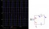
I also saw that when R->0, then the current never changes sign, why is that?
Its all got to do with how R's size affect IL, could you explain it please?
Hello there,
You did not see the current go through zero because you did not run
the simulation long enough. Unfortunately, with a resistance so small
like that you may need to run it very long in order to see the current
actually go through zero. If you instead increase the size of R a bit
you will see it go through zero as you probably expect.
The reason for this behavior is because when we do a transient
analysis with a sine source and an inductor and resistor there is
really another source in there that we dont see, and that is a
unit step function. Thus, the sine source is two sources in one,
not just a sine source like this:
v=u(t)*sin(t)
In order to get around this the sine source would have had to be running
in the circuit for all time since t=-infinity so that when we get to t=0
(where most analysis starts) all the effects of the u(t) source have
had time to dissipate. To simulate this, simply run for a much longer
time and look at the current wave after much time has past, then compare
to what it looks like around t=0.
Another way around this sometimes works is to set the initial current
in the inductor to some non zero value before starting the analysis
so that the u(t) part is canceled out at t=0.
We can ordinarily do an AC circuit calculation that involves only a sine
source but the answer we have to remember is the answer we get
after the circuit reaches steady state and does not represent the
entire response of the circuit...
I=amplitude(V/Z)
where
Z=j*w*L+R
The current i think you are looking for is I above.
Oh yeah, another way to get around the u(t) problem is to use a cosine source
instead of a sine source. You'll get the same response except it will be phase
shifted by 90 degrees.
To do this, you may have to set your sine source to have a phase shift of +90
degrees, or pi/2 radians because your software may not have a cosine source.

")