Continue to Site

Welcome to our site!

Electro Tech is an online community (with over 170,000 members) who enjoy talking about and building electronic circuits, projects and gadgets. To participate you need to register. Registration is free. Click here to register now.

  • Welcome to our site! Electro Tech is an online community (with over 170,000 members) who enjoy talking about and building electronic circuits, projects and gadgets. To participate you need to register. Registration is free. Click here to register now.

Increasing Voltage of a transformer

Status
Not open for further replies.

narcissus

New Member
Greetings Everyone,

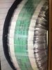
My first post here. I have a pair of toroidal transformers which are utilised in my power amps (monoblocks), please have a look at the picture for complete ratings.

I would like to increase the voltage to 27V from the existing 19V, will I have a problem or is this totally doable by up winding the required turns?

Thank you
 

Attachments

  • image.jpeg
    image.jpeg
    969.1 KB · Views: 129
I would like to increase the voltage to 27V from the existing 19V, will I have a problem or is this totally doable by up winding the required turns?
Yes it is possible.
But there are a couple of traps.

Is there enough room through the centre of the toroid for the extra windings?

The transformer appears to be rated at 1000VA (Two 19v x 26A secondary windings)
If you increase the voltage per winding from 19 to 27v, the current rating will reduce to 26 x (19/27) = 18 Amps.

JimB
 
Thank you for replying Jim, much appreciated.

Yes there is enough room for the extra windings.

Absolutely, the transformer is rated 1000VA (two 19v X 26A secondary windings). So what are the cons if the current ratings reduce to 18amps?
 
If your required output current is less than 18 amps then you don't have a problem. If you need more than 18 amps then the transformer will be overloaded.

Les.
 
Thank you for replying Jim, much appreciated.

Yes there is enough room for the extra windings.

Absolutely, the transformer is rated 1000VA (two 19v X 26A secondary windings). So what are the cons if the current ratings reduce to 18amps?

another thing to be careful about, i've had some experience repairing toroids with shorted windings, and the power line winding is generally the outer layer... not always, but if it is, make sure you take pictures so you know how many turns, and their spacing.

also, a question... are you changing any of the other components in the amp, or just trying to boost the supply voltage?
 
i gather these are in parallel with the originals? can the driver circuit drive the extra 12nF of gate capacitance? (original gate capacitance of 14.4nF, total gate capacitance with 72 MOSFETS will be 26.92nF. also be aware this will likely require a change of the compensation cap in the voltage amplifier stage, or the amp could become unstable. also, in order to maintain the same clipping point with reference to input level, you also need to change the feedback resistor to change the voltage gain of the amp. i'm not saying 100% that those will be problems, but if you do have some problems with the amp after modification, you have some places to look for a solution...

actually, now that i think of it, you don't even have to take the transformer apart, you can add your extra windings on the outside, and put them in series with the original secondary. just make sure you are in the right ballpark with the wire gauge used on the secondary, and that they are wound in the right direction so they aren't out of phase with the secondary (you can determine this by feeding the primary with a signal generator and seeing if the added turns boost or buck the secondary). after adding the extra turns, and getting them phased correctly, wind a layer of kynar or mylar tape around them to protect them.
 
I have modified several toroids from removing/adding turns to adding small over-winds for aux voltages etc.
In every case the power winding has always been wound on first.
The ratio is around 2 turns/volt, if a precise value is needed first, just wind on about 10 turns and measure the voltage.
Max.
 
i've got one here where the primary was on the outside, and that's the most recent one i rewound... i was lucky too, the shorted turn was only about 10 turns from the end.
 
Yep I've seen the primary on the outside too, I think its so the highest current winding, ie the secondary is nearest the core.
 
i saw an interesting thing happen at a music store with a toroidal transformer. originally the toroid had a bolt that went through the bottom cover to the top cover, with a plastic washer on the top cover under the nut. guess what happens when the plastic washer is missing? the chassis of the amp becomes a shorted turn and blows the fuse. when there's a toroid inside a chassis, and the top cover gets dented to where the top cover makes contact with the bolt, same thing...
 
Yep I've seen the primary on the outside too, I think its so the highest current winding, ie the secondary is nearest the core.
If the secondary is lower voltage then usually the primary is going to be the lowest current winding?
I have been modifying them for some 50yrs now and never seen a primary on the outside winding.
Max.
 
i saw an interesting thing happen at a music store with a toroidal transformer. originally the toroid had a bolt that went through the bottom cover to the top cover, with a plastic washer on the top cover under the nut. guess what happens when the plastic washer is missing? the chassis of the amp becomes a shorted turn and blows the fuse. when there's a toroid inside a chassis, and the top cover gets dented to where the top cover makes contact with the bolt, same thing...

The ones I have purchased normally have a metal retaining disc on the top under the mounting bolt, and yes I have seen some instances where some have modified the mounting so that the top of the bolt has a clamp contacting the frame of the enclosure essentially creating a shorted turn and overheating.
Max.
 
i gather these are in parallel with the originals? can the driver circuit drive the extra 12nF of gate capacitance? (original gate capacitance of 14.4nF, total gate capacitance with 72 MOSFETS will be 26.92nF. also be aware this will likely require a change of the compensation cap in the voltage amplifier stage, or the amp could become unstable. also, in order to maintain the same clipping point with reference to input level, you also need to change the feedback resistor to change the voltage gain of the amp. i'm not saying 100% that those will be problems, but if you do have some problems with the amp after modification, you have some places to look for a solution...

actually, now that i think of it, you don't even have to take the transformer apart, you can add your extra windings on the outside, and put them in series with the original secondary. just make sure you are in the right ballpark with the wire gauge used on the secondary, and that they are wound in the right direction so they aren't out of phase with the secondary (you can determine this by feeding the primary with a signal generator and seeing if the added turns boost or buck the secondary). after adding the extra turns, and getting them phased correctly, wind a layer of kynar or mylar tape around them to protect them.

Noted, the amps have been modded and playing music already.

Yes, that's exactly what I had in mind..
 
My bad, I meant to say the highest current winding is nearest the core.
 
another thing to be careful about, i've had some experience repairing toroids with shorted windings, and the power line winding is generally the outer layer... not always, but if it is, make sure you take pictures so you know how many turns, and their spacing.

also, a question... are you changing any of the other components in the amp, or just trying to boost the supply voltage?

The input stage current is set at 2.85V so each rail is 27v thereabouts , 54v rail to rail...
 
I have modified several toroids from removing/adding turns to adding small over-winds for aux voltages etc.
In every case the power winding has always been wound on first.
The ratio is around 2 turns/volt, if a precise value is needed first, just wind on about 10 turns and measure the voltage.
Max.

Duly Noted, thanks for the input.
 
27V RMS has a peak of 38.2V and a bridge rectifier reduces it to 36.2VDC. The output Mosfets might have a 2V loss so the output swing will be 64V p-p maximum which is 22.6V RMS. Then the power in an 8 ohm speaker is only 64W or 128W into 4 ohms.
If the amplifier is class AB then each amp heats with about 110W for a total of 238W. Then this monster of a toroid transformer can power four of these 128W into 4 ohms amplifiers almost at clipping continuously.
 
So my local vendor reverted with this message

"About up winding of Toroidal that is 19 Volt to 27 Volt. Its not technically possible. Coz your existing power rating changes from 1000 VA. To 1500 VA.

If we do this then your primary winding will be damaged."

Can someone please confirm if this claim is indeed true?
 
Status
Not open for further replies.

Latest threads

New Articles From Microcontroller Tips

Back
Top