Continue to Site

Welcome to our site!

Electro Tech is an online community (with over 170,000 members) who enjoy talking about and building electronic circuits, projects and gadgets. To participate you need to register. Registration is free. Click here to register now.

  • Welcome to our site! Electro Tech is an online community (with over 170,000 members) who enjoy talking about and building electronic circuits, projects and gadgets. To participate you need to register. Registration is free. Click here to register now.

Increasing 386 output

Status
Not open for further replies.
joecool85 said:
they won't overheat driving a 4ohm load when bridged.
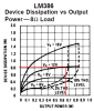
Oh yeah? They are seriously overloaded with the poorly recommended 4 ohm speaker. The very high supply voltage of 12V makes their heating even worse. They each produce an output of only 1.5Vp-p. Where does the remaining 10.5V go? HEAT! Try it. Feed them a sustain and turn up the volume to just below clipping. I figure that each LM386 will try to dissipate a whopping 2.8W and they will smoke.

**EDIT**
And besides that, a lm386 chip will output around 500mw running at 9volts and pushing an 8ohm load.
It is designed for a single (not bridged) IC driving an 8 ohm load and a 6V or 9V battery. Look again at the datasheet and you will see its output is a min of 500 milli-whats. "Whats" are square-wave output with a horrible-sounding 10% distortion. It is a min of only 350mW to 400mW at clipping. Flea power.

A TDA1554 (and many others) bridged power amplifier IC is used in car radios and gives a low distortion output of 14 real watts to a 4 ohm speaker with a charging 12V battery. Enough to blow your ears off if you are close to the speaker!
 
Nigel Goodwin said:
Also, as there's no feedback in the design, the two halves of the amps aren't balanced - so distortion will be far higher than a single amp
Actually, the LM386 does have built-in negative feedback. Its gain is 20 without the capacitor from pin 1 to pin 8 and 200 with the capacitor. The bridged circuit has the caps so has the high gain and the balance isn't bad, a gain of 200 on one of the amps and "only" 199 on the inverting side.

Without a load, the distortion of an LM386 is nearly unmeasurable. It is used in "headbanger" headphones amps driving 32 ohm or 600 ohm headphones with very low distortion. In this circuit that is bridged and with its dead-short of a 4 ohm speaker, its distortion is probably pretty high.
 
Ok, I'm not saying this thing is a killer amp, but it works fine to practice guitar on. And personally I've only built the little gem which uses a single 386, but I know several others that have built the bridged model. Maybe when you are only playing guitar on it, it doesn't matter? But from what I understand, its harder on a chip using it for guitar than for regular am/fm etc. I've run mine on 12volts at 8ohms for hours with little/no heat out of the 386, NO heatsink at all. It could have to do with the fact that the incoming signal is only something like 0.4volts or so out of humbucker pickups. Not sure, I'm not an electrical engineer or anything. And I didn't mean to come off as an ass when I first posted saying that you guys don't know about bridging the lm386, I was amazed at how many people were saying that it couldn't/shouldn't be done, when I know at least 5-6 people that have done it with no problem. Most of them use their Little Gem MKIIs to drive 2x12 guitar cabs no less!

Don't believe me, check out diystompboxes.com

Also, I know about guitar amps more than it seems you guys think. My own regular practice amp is a Dean Markley K-20, a 15wRMS amp with an 8 inch speaker. But I've played a Peavey 212 with 250wRMS and built in 2x12. I'm not saying I'm any guitar amp guru either, but I do know a fair amount. I'm planning on building a lm3886 based chipamp for the poweramp section of my next guitar rig.
 
joecool85 said:
Ok, I'm not saying this thing is a killer amp, but it works fine to practice guitar on. And personally I've only built the little gem which uses a single 386, but I know several others that have built the bridged model. Maybe when you are only playing guitar on it, it doesn't matter? But from what I understand, its harder on a chip using it for guitar than for regular am/fm etc. I've run mine on 12volts at 8ohms for hours with little/no heat out of the 386, NO heatsink at all.

But that's a single ended amp, feeding a sensible impedance, so no problem - try adding three more 8 ohm speakers in parallel with your existing one and see the difference - THAT'S what the bridge circuit is doing with a 4 ohm load.

Guitar isn't that hard on an amp, there's no real low frequencies (bass is fairly hard on amps), and it obviously depends on what's been played and what style. If you're overdriving a power amp it's bad regardless of the instrument, and you should look at valve amps for that.

The worst instrument is probably keyboard?, because you can get loud sustained single notes - which can mess up the power distribution of your cross-overs.

It could have to do with the fact that the incoming signal is only something like 0.4volts or so out of humbucker pickups. Not sure, I'm not an electrical engineer or anything. And I didn't mean to come off as an ass when I first posted saying that you guys don't know about bridging the lm386, I was amazed at how many people were saying that it couldn't/shouldn't be done, when I know at least 5-6 people that have done it with no problem. Most of them use their Little Gem MKIIs to drive 2x12 guitar cabs no less!

Don't believe me, check out diystompboxes.com

Nothing to disbelieve - I've no problem feeding a 2x12 from an LM386. the size of the speakers doesn't matter, it's their impedance that does! - an 8 or 16 ohm 2x12 will be fine (obviously 16 ohm is preferable though). Large speakers will most probably be louder as well!.

As for "shouldn't" be bridged, I would certainly say not, it's a really poor idea, and very low quality - you could easily build something much better with no more effort.
 
Didn't you try my "smoke test" with a continuous sustain at clipping?

The graph for the voltage output of an LM386 that I posted before shows that it produces 660mW at clipping into an 8 ohm load with a 12V supply. The power dissipation graph I am posting now shows 820mW of heat.
Its spec's show a thermal resistance of 107 degrees per watt so its chip temp with a 25 degrees ambient is 112.7 degrees C. Its max internal temp is 150 degrees C.
YOU ARE RIGHT, it doesn't get too hot in your application! :lol:

EDIT: With a 4 ohm load, your LM386 with a 12V supply will produce only 450mW at clipping, and 1.3W of heat, way off the end of its graph.
 

Attachments

  • lm386_469.png
    lm386_469.png
    26.2 KB · Views: 506
Well, its good to hear all this stuff from you guys. I really hadn't talked to any electronics people really, only guitarists that their hobby is electronics on the side (like me.) I make overdrive/distortion pedals when I get bored lol.
 
Hi Joe,
We never get bored because we are always analysing an building stuff.
Post the schematic of one of your overdrive/distortion circuits and we will simulate it to show how good/bad it looks on a 'scope.
Here is a sim of a Hendricks circuit with a pure sine-wave input:
 

Attachments

  • sim-_fuzz_face_133.png
    sim-_fuzz_face_133.png
    22.5 KB · Views: 496
This is one that I designed myself.

**broken link removed**

And the first one I built was actually very similar to what you just showed for a fuzz face. Mine used germanium trannys instead of 2n3904s. Along with a couple different resistor values.[/img]
 
One uses LEDs as diodes, the other uses 1n914s. It sounds *almost* the same using one or the other, but I found that I like it with both.
 
The LEDs won't do anything with the diodes in parallel with them. Therefore the 1st transistor doesn't do anything.
 
First off, why don't they do anything?

Second off, someone that built my pedal (I posted the schematic on diystompboxes.com) had said the same thing, but then tried it and noticed a difference when using both trannys.

here is the link:
**broken link removed**
 
The LEDs won't do anything with diodes in parallel with them.
The sim looks like an ordinary "soft clipper":
 

Attachments

  • joe_s_fuzz_circuit.png
    joe_s_fuzz_circuit.png
    23.6 KB · Views: 472
Well, first of all, you changed the schematic.

It uses MPSA13s, which are darlington trannys, unlike 2n3904s.

Also, Q1 doesn't feed into Q2 like you show, both bases are connected to input line only. They are running in parallel.
 
joecool85 said:
Well, first of all, you changed the schematic.

It uses MPSA13s, which are darlington trannys, unlike 2n3904s.
My simulation software doesn't have a small darlington, so I made one with two 2N3904 transistors. Same thing.

Also, Q1 doesn't feed into Q2 like you show, both bases are connected to input line only. They are running in parallel.
Transistors in parallel work only with the strongest one and the weakest one does nothing. Therefore I used only a single darlington.

An LED needs 1.8V or more to function. The ordinary diodes in parallel with them limits the voltage to 600mV so the LEDs do nothing.

Your circuit has a symmetrical clipped waveform, therefore doesn't produce even harmonics. The Hendricks circuit I posted has an unsymmetrical waveform, therefore produces all harmonics.
 

Attachments

  • mpsa13.png
    mpsa13.png
    12.1 KB · Views: 454
nm, I would have known that if I thought about it lol. I still don't know why, but for some reason it effects the guitar's sound using one on tranny or both...
 
The small capacitance of the 2nd darlington might cut the high frequencies a little. So would a small capacitor.
The LEDs didn't light, right?
 
Correct, no light from the LEDs. And you may be right. I'll have to play with it some more when I get the chance.

**edit**
What do you think would happen using one 1n914 and one LED for diodes on a single MPSA13 circuit?
 
joecool85 said:
What do you think would happen using one 1n914 and one LED for diodes on a single MPSA13 circuit?
Sorry, I didn't save my simulation so I can't try it with different diodes. It would probably make both even and odd harmonics, and the LED will light continuously if it is one of them and only when you play if it is the other one.
 
Status
Not open for further replies.

Latest threads

Back
Top