Continue to Site

Welcome to our site!

Electro Tech is an online community (with over 170,000 members) who enjoy talking about and building electronic circuits, projects and gadgets. To participate you need to register. Registration is free. Click here to register now.

  • Welcome to our site! Electro Tech is an online community (with over 170,000 members) who enjoy talking about and building electronic circuits, projects and gadgets. To participate you need to register. Registration is free. Click here to register now.

Inchworm 1.5 reed relay mod (Switched +5V on Target)

Status
Not open for further replies.

blueroomelectronics

Well-Known Member
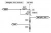
I've been experimenting with one of my Inchworms and added a Radio Shack Reed Relay across RA4 (16F877 pin 6) and +5 (with a 1N4148 kickback diode) Two trace cuts (4.7K 1% *near the TP+5) and the +5V on CON1. I'll publish photos and info if anyone else needs this mod.


Would you like this mod in the next Inchworm design? Is it worth $5 extra?
**broken link removed**
 
Please post the mod.

Modify the board so it can be built both ways.
To build it without the relay have the user add jumpers in place of the relay.

That way you can keep the cost down and allow the relay to be added when/if needed.

If you would like help proofing the Robin Instructions PM me. Sounds like a neat device.

3v0
 
Aren't Inchworms generally battery powered? Relays are more useful for line powered devices, I mean they're great on general purpose I/O boards but I'm not sure what you could use one for that you couldn't use a small H-bridge that would fit in close to the same space and be able to be switched faster and more reliably.
 
William:

Sounds cool to me. Will this fix the MCLR issue (allow MCLR_off and internal oscillator on)?

-LP
 
The mod functions to disconnect the +5V from the target CON1 (ICD2). I've not tried it with the mclr & intrc clk enabled although MPLAB still warns me not to. The relay coil (20ma) connects between +5 and the 16F877 RA4 (pin 6). The contacts connect to +5, R3 (top) and CON1 (+5V). A small 1N4148 diode should be added across the coil contacts (cathode to +5).
I can incorporate the relay or jumper mod into Inchworm II (PLCC 16F877A and PLCC 18F4550 optional) It will be slightly more expensive than the current Inchworm but upgradable to USB (just add the 18F4550, crystal and a couple of small parts) The 18F4550 is not a cheap chip.
**broken link removed**
 
Whats the function of this mod - you said it disconnects the 5V from CON1 - why not just not use the 5V when you connect CON1 to your pic circuit - what am I missing? :)
 
gregmcc said:
Whats the function of this mod - you said it disconnects the 5V from CON1 - why not just not use the 5V when you connect CON1 to your pic circuit - what am I missing? :)

Yes, you're missing the point!.

A programmer really needs to switch the 5V supply to the target device, which the InchWorm currently doesn't do - this restricts the config fuse options in devices like the 16F628 - where you can disable the MCLR pin and use it as I/O.

The ICD2 software already includes this facility, but it wasn't implemented in the InchWorm hardware.
 
blueroomelectronics said:
Would you like this mod in the next Inchworm design? Is it worth $5 extra?

If you shop around, you can find reed and/or DIP relays for more like $1-2. However, is there any reason you can't implement the same thing using a transistor, since you'll be changing the design anyway? I haven't delved into the details, but the USB ICD2 clone that I have just uses a PNP transistor to switch Vcc, according to the schematic.
 
Seems like an awful lot of trouble and expense when all you need is a P-channel MOSFET and a resistor (or a PNP transistor and two resistors)? Duh!!!

(the two analog voltage divider resistors in the pic' below should already be on the board though they're probably connected to a "hard" 5v signal)...
 

Attachments

  • Target VDD Switch Final.jpg
    Target VDD Switch Final.jpg
    23.3 KB · Views: 211
I'll look into the BS250P, you've posted it before I should learn to listen. I was concerned about the 230ma drive source be too small. Is there a 400ma pfet thats commonly available?
Thought #2 is use a PTC to limit current and remove the 7805 alltogether. So it's USB power plus RS232 (basic) and with the 18F4550 it's USB all the way.
Mike did you build a 18F4550 ICD2? I see there are some with a single 20MHz and some with 16MHz & 20MHz
 
I only just started building my USB ICD2. I have stopped to consider adding the three 74LS12x parts so that I can support the 3.3v devices.
 
The USB ICD2 clone I built was from the PiCS rev B design at icd2clone.com - it uses a single 20MHz crystal. It doesn't have the buffers as some designs do, so it can't do the 3.3v parts, but I don't foresee myself using those any time in the near future anyway.
 
Mike said:
That's the same design I started building too Evan (with a single 20-MHz crystal)...

in that case, make SURE you solder some 0.1uF decoupling capacitors directly across the power traces of each of the PICs. The design doesn't include them, but mine did not work until I added them. I used some 0805 surface-mount capacitors which fit perfectly between the traces underneath.
 
Evandude, do both the 16F877 and the 18F4550 use 20MHz ? I've seen designs use 16MHz on the 18F4550. Does one version reqiures modified 18F4550 firmware?
 
blueroomelectronics said:
Evandude, do both the 16F877 and the 18F4550 use 20MHz ? I've seen designs use 16MHz on the 18F4550. Does one version reqiures modified 18F4550 firmware?
Yes, they both use 20MHz - that's the only crystal on the board. The xtal is connected directly to the 18F4550, and its OSC2 pin is also connected to the OSC1 pin of the 16F877A.
 
evandude said:
Yes, they both use 20MHz - that's the only crystal on the board. The xtal is connected directly to the 18F4550, and its OSC2 pin is also connected to the OSC1 pin of the 16F877A.

So why does it have two PIC's on board?.
 
Nigel Goodwin said:
So why does it have two PIC's on board?.
To the best of my knowledge:
ICD2's were originally serial, using an 16F877, and then microchip released a USB ICD2 - it used a USB interface chip of some sort (I think it was a cypress? or something like that) along with the same 16F877. Later, they stopped using that interface chip and replaced it with an 18F4550. Basically, the 18F4550 is serving solely as a link between USB and the 16F877, and the 16F877 is doing all the actual debugging work, as it always did in the serial versions.

The 18F4550 might be able to do the whole job by itself, though it would require a lot of coding to write the firmware for it - however, the USB functionality does consume a lot of processing time and needs to be serviced very frequently, which might interfere with its ability to perform debugging tasks. All I know is that microchip still hasn't combined it all onto one chip, and I am assuming that there's a reason for that (other than laziness)

But, even if it could be done, it wouldn't make sense for a hobbyist to attempt it - part of "cloning" microchip's ICD2 is that it lets new firmware be downloaded to the board automatically from MPLAB, and any time they release an updated firmware, you can use it immediately - if a hobbyist modified the whole thing to run on a single chip, even if MPLAB actually accepted it as a valid ICD2, they'd be in trouble any time they needed to update the firmware.
 
Last edited:
Status
Not open for further replies.

Latest threads

Back
Top