Odysseas
Member
Hi everyone,
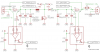
I'm trying to build a solar charger, using a simple boost configuration. To sense the current coming from the solar panel and going into the battery, I use two INA139 current monitor chips. See schematic. The supply voltage V+ is derived from V+_BATTERY_H through a little bit of filtering (V+ is about .7V below V+_BATTERY_H). The output current from the INA139 is run through a 100k resistor each to generate an analogue voltage proportional to the current (1V = 1A). HS1 and HS2 are just heat sinks for the diode and MOSFET.
However, the current monitors start drawing way too much current the instant power is applied. I tried ramping up the battery voltage through a PSU (no solar panel connected) and at one volt, the current draw is already about 100mA. I checked for short circuits and everything, nothing. Initially, I had only the right hand side INA139 populated, then only the one on the left side of the schematic - both show the same behaviour. One has now disappeared in smoke. At one point, D4 wasn't populated yet and the left hand side INA139 didn't draw too much current. This would suggest that the problem only appears when pins 3 and 4 on the chip see any voltage above ground.
What could be going on here? Thanks for any help.