Continue to Site

Welcome to our site!

Electro Tech is an online community (with over 170,000 members) who enjoy talking about and building electronic circuits, projects and gadgets. To participate you need to register. Registration is free. Click here to register now.

  • Welcome to our site! Electro Tech is an online community (with over 170,000 members) who enjoy talking about and building electronic circuits, projects and gadgets. To participate you need to register. Registration is free. Click here to register now.

In need someone to write me a code...

Status
Not open for further replies.

dailydriver

New Member
Ok. I'm not a programmer. I've tried to work with PIC's, but got too confused. I've purchased a PICKit II and is still lost.

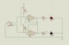
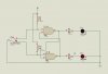
I'm just looking to get something to work like this:

It's going to have a ground input. I want it to have two outputs with one input. They are all low signals.

I want it to switch between the two outputs everytime the input is seen. Basically, I want it to alternate between the two outputs everytime I trigger the input. All the signals should be low.

I have access to a lot of PIC12F508. If anyone can write me a short code. I would appreciate it. If not, I will buy the pic that the code is written for also. I figured, there isn't much I/O's used, so the 12F508 should suffice.

I'm an electronics technician, but when it comes to coding. I have no clue.
 
Your description of what needs to happen is not clear.

Is this right?

1 input and 2 outputs

if one output is high the other must be low

when you see the input line go low, make the high line low, and the low line high
 
Having someone write your code is a poor approach, what happens when you are asked to change it?. Check out Gooligum for the baseline (i.e Pic12f508) step by step tutorials.
 
I'm in the process of learning, but I need this right now to run a remote control.

1 input, 2 output.

Here's what I need.

Input Output1 Output2
0 0 X
0 X 0
0 0 X
0 X 0

If input has ground applied to it. Output1 should show as ground and Output2 should not have any signal on it. (If it's possible)
If input has ground applied to it again. Output2 should show as ground and Output1 should not have any signal on it.
and on and on....

Basically, I'm looking to use it as a flip flop to drive a couple of switches alternatively and I only have one switch that produces a ground signal if inverted. And those switches works by monitoring for a ground signal.

I only have one button, so I am trying to get away with just using one button to control both devices alternatively.
 
Hi,

A simple switch debouncer / flipflop will meet your specifications, no need for a micro unless you need to develop things further.

If you do, what have you tried and what language did you use.

There is no such thing as no voltage unless you power the whole circuit off , you simply have to drive the output in one state H or L like most things digital.
 

Attachments

  • ScreenShot001.jpg
    ScreenShot001.jpg
    21.2 KB · Views: 178
  • ScreenShot002.jpg
    ScreenShot002.jpg
    21.1 KB · Views: 181
Then why don't you use a simple flip-flop, hook the button to it via a shmidt-trigger (or similar for debounce), and use the outputs of the flip-flop to control whatever you are attempting to control?
 
Thanks, I forgot that it will always have a high if not low. I'll come up with a circuit and see.

"wp100", thanks for ths diagram. I was hoping a PIC might be simpler.
 
Processor outputs, when turned to inputs are perfect for the " HiZ state " ...

so, "Logic" (!) possible states are LOW, FLOATING or HIGH ....

Alain
 
This may or may not be a lot of use... I looked at the Microchip offerings and found them very confusing. On the other hand, MikroElektronika do some great boards. I've got an EasyPIC6, which came pre-populated with a PIC16F887, and their free compilers are more than adequate for learning from. A bit pricey, but very well designed and presented.

This works fine on my EasyPIC6. I used PORTB for input as it has weak pullups, if you want to connect it to a switch that is either grounded or open circuit. PORTA is output; there is no open collector/drain on this PIC so I just set the port to 1 or 0. If you want OC/OD you could always hook each output up to a transistor: connect B to the PIC, E to GND and C to the output: when PORT is 1, the transistor is on and the collector grounded; when PORT is 0, the transistor is off and the collector OC.

By the way I like state machines. There's probably a more condensed way of writing it, and you could hand code it in assembler if you really want, but the project doesn't really need that.
Code:
/*

One input two outputs
Initial state both outputs low.
Remain at this state while input is high.

When input is grounded, O1 goes low, O2 high
Remain at this state while input is grounded, and when it goes high
When input is grounded, O1 goes high, O2 low
Remain at this state while input is grounded, and when it goes high

RB0 is input (because PortB has weak pullups; J17 is set to pull to ground)
RA0,RA1 are outputs
*/
void main()
{
  char stat;
  ANSEL  = 0;              // Configure AN pins as digital
  ANSELH = 0;
  WPUB=1;                  // enable pull-up resistors
  TRISB=1;                 // enable PORTB.0 as input
  TRISA=0;                 // PORTA 0,1 output
  PORTA=0;                 // initial state both outputs low
  stat=0;
  for (;;)
  {
    switch (stat)
    {
    case 0:
      if (PORTB & 1)
      {
        // button is up, do nothing
      }
      else
      {
        // button is pressed; go to stat=1 and debounce
        Delay_ms(100);
        stat=1;
        PORTA=2;
      }
      break;
      
    case 1: // Button is down, A0=0, A1=1
      if (PORTB & 1)
      {
        // button is up; go to stat=2 and debounce
        Delay_ms(100);
        stat=2;
      }
      else
      {
        // button is down; remain here
      }
      break;
      
    case 2: // Button is up, A0=0, A1=1
      if (PORTB & 1)
      {
        // button is up; do nothing
      }
      else
      {
        // button down; go to stat=3 and debounce
        Delay_ms(100);
        stat=3;
        PORTA=1;
      }
      break;
      
    case 3: // button is down, A0=1, A1=0
      if (PORTB & 1)
      {
        // button is up, go to stat=4 and debounce
        Delay_ms(100);
        stat=4;
      }
      else
      {
        // button is down; stay here
      }
      break;
      
    case 4: // button is up; A0=1, A1=0
      if (PORTB & 1)
      {
        // button is up, do nothing
      }
      else
      {
        // button down; go to stat=1 and debounce
        Delay_ms(100);
        stat=1;
        PORTA=2;
      }
      break;
    }
  }
}
 
Toggle a pair of outputs on each "new press", yes?

Code:
  portb = 2;                    // initialize outputs
//
//  swnew  __---___---___---_____  sample active low switch
//  swold  ___---___---___---____  switch state latch
//  delta  __-__-__-__-__-__-____  changes, press or release
//  press  __-_____-_____-_______  new press bits
//
//   RB0   ___------______-------
//   RB1   ---______------_______
//
  while(1)
  {
    delay_ms(25);               // 25-msec debounce interval
    swold = swnew;              // update switch state latch
    swnew = ~portb;             // sample active lo switches
    delta = swnew ^ swold;      // changes, press or release
    press = delta & swnew;      // filter out 'release' bits
    if(press.4)                 // if "new press" on RB4 switch
      portb ^= 3;               // toggle RB1 and RB0 outputs
  }
 
Last edited:
yeah it occurred to me about 2.30 am that the whole thing could probably be done in 5 lines just by looking for a high->low transition on the input ;-)
Oh well.
 
ooh you old cynic you. Actually I got up in the middle of the night for a tinkle and that's when the thought crossed my mind.
Hey, here's a thought. If I'm on the throne and reading a programming book, is that a hex dump?
 
Status
Not open for further replies.

Latest threads

New Articles From Microcontroller Tips

Back
Top