Continue to Site

Welcome to our site!

Electro Tech is an online community (with over 170,000 members) who enjoy talking about and building electronic circuits, projects and gadgets. To participate you need to register. Registration is free. Click here to register now.

  • Welcome to our site! Electro Tech is an online community (with over 170,000 members) who enjoy talking about and building electronic circuits, projects and gadgets. To participate you need to register. Registration is free. Click here to register now.

In Car Computer Project

Status
Not open for further replies.

jbarnes77

New Member
Hi Everybody.

I've got a VM110 USB Experiment Interface Board to play around with, which takes external inputs, and via the USB, brings them into the world of software.

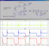
What I'd like to do is take the 12v pulse from the coil (negative) in my classic mini, and use the USB board to read the pulse in... for a RPM reading.

Now this USB interface has a few inputs. basically you get a 1 when INPUT 1 is connected to the GND, and 0 when it's not, same goes for INPUT2 - GND, etc...

So, I thought i'd need some sort of relay that trigger's the on/off state.
I think the RPM pulse could be upto 200 pulses per second, Am i right in thinking normal car relays are too slow? I'm more computers than electronics so i'm not 100% sure what to do?

hope someone can help,
much appreciated

Jon.
 
Jon, this will work but you want to stay away from the coil signal. There are some really nasty transient voltage excursions (+_250V?) across the primary. If you have a storage scope with a 10X probe, go look and you will see what I mean. It will take a fairly complicated network with R,C, and Zener clamping diodes to clean it up to where you can feed it into 5V logic. Using a pulse transformer with two windings is a good idea to eliminate common-mode ground noise if you must use the voltage across the coil as the source of your signal.

If you dont have access to a scope, follow the wire which switches the coil. It usually is done by a big switching transistor (Bipolar or FET) in a Coil Trigger Module. Try to locate the signal that triggers this module. It usually comes directly from the ECU and is a "logic" signal. A wiring diagram and a scope is the best way to look at this...
 
Last edited:
Hi Mike,
I'm afraid you lost me at storage scope. :(

unfortunately there isnt' an ECU in the mini, its all old school mechanics.
So the signal would have to be taken from the negative point on the coil.

thanks

Jon
 
Hi Mike,
I'm afraid you lost me at storage scope. :(

"scope" is an Oscilloscope.

Storage scope is one which can store relatively slowly varying events for subsequent viewing. At idle speed, ignition signals in a normal car happen just slowly enough to make them hard to view with a conventional o'scope.


Ok, I did this once. It seems I used a network sort of like this:

The zener is 4.7V.
 

Attachments

  • Ignition.gif
    Ignition.gif
    57.9 KB · Views: 154
Status
Not open for further replies.

Latest threads

New Articles From Microcontroller Tips

Back
Top