Continue to Site

Welcome to our site!

Electro Tech is an online community (with over 170,000 members) who enjoy talking about and building electronic circuits, projects and gadgets. To participate you need to register. Registration is free. Click here to register now.

  • Welcome to our site! Electro Tech is an online community (with over 170,000 members) who enjoy talking about and building electronic circuits, projects and gadgets. To participate you need to register. Registration is free. Click here to register now.

IGBT not switching in H Bridge. Is it a driver problem?

Status
Not open for further replies.
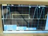
Hello I am designing a sinewave inverter using IGBTs in H bridge configuration. DC bus voltage is 325 V but for testing purpose I am using 75 VDC ( using 6 batteries ) as can be seen in DSO waveforms. Also I have reduced the switching frequency to 10 hz for testing ( actual will be 4 to 6 Khz ).
I haven't connected any load at the output of the bridge also after blowing so many IGBTs I have disconnected pulse to both lower IGBTs gate driver and one of high side Igbts drive ( gate drivers still connected to pull down the gates of the three IGBTs ). So I am now giving pulses to only one of the high side IGBTs driver.
I have read some app notes from which I assume IGBT is bieng turned on due to internal voltage divider network of capacitors Cge and Cgc. I am completely lost. What I am missing? Any suggestions? Here are the waveforms-
 
Waveforms-
 

Attachments

  • 20180914_085855.jpg
    20180914_085855.jpg
    254.5 KB · Views: 269
It's just a simple H bridge. And yellow is the waveform of the gate of the high side IGBT and blue is the waveform of the drain of the same IGBT.
 
the waveform of the drain of the same IGBT.
The collector of a high-side IGBT would normally be at the supply rail voltage (fixed 75V). Why does yours have a waveform?
Does your driver have a bootstrap circuit to raise the IGBT gate voltage sufficiently above its emitter voltage?
I can't quite follow how you've got things configured, but take care that you don't exceed the maximum gate-emitter voltage of any of the IGBTs.

Maybe the OP is unaware there are both P-type and N-type devices in a "simple" H-bridge and tried wiring up all N-type IGBTs the same way in his not-so-simple H-bridge. Either way, we need a schematic. He's missing something basic.

I am fairly certain his scope probes are not differential which would mean everything is being measured relative to ground which is wrong. But he has given us nowhere near enough info.
 
Last edited:
Maybe the OP is unaware there are both P-type and N-type devices in a "simple" H-bridge and tried wiring up all N-type IGBTs the same way in his not-so-simple H-bridge. Either way, we need a schematic. He's missing something basic.

Or he has both the low and high on one side on at the same time, "shoot through".
 
Bootstrap bias is always made using low side PWM with cap to Vbs to bias higher than Vdc when using all N types. Deadtime must chosen to prevent shoot thru and lowest ESL paths are needed in any local current loops
 
Sorry for the late reply. All the IGBTs used are N type and the drivers are powered from isolated supply so no bootstrap.
DSO probes' ground connected to emmiter, blue one to collector and yellow to gate. IGBT is perfectly switching on as you can see when yellow (gate) is high VCE is zero but at turn off when yellow is low we see IGBT is still turned on for some time and slowly turns off then on again.
 
Sorry for the late reply. All the IGBTs used are N type and the drivers are powered from isolated supply so no bootstrap.


I have 8 circuits like that sitting beside me that fit that description and they all work, so obviously you're not telling us something or your circuit is wrong.

We need to see the circuit. Otherwise it will be a guessing game as this entire thread has been. There is no point continuing responding to you until you give us your circuit.
 
Last edited:
You have point B tied to ground, so the gate of the top left IGBT can never get above 15V with reference to the -Bus (which is also grounded).
When posting a schematic, please use component designators so that we know which component is being discussed.
 
It is common for this error. Please check because we are missing details.
>"OV" at TLP350-pin5 connected to "-Bus0V"?
>TLP350-pin5 left side connected to TLP350-pin5 right side? (one or two supplies?)
>Top IGBT Gate voltage more than 20 volts. (see data sheet 20V max) EDITED THE SUPPLY IS 15v NOT 25v
>Do you have 7 to 10mA in 560 ohm resistor into TLP350-pin2? Remember the input voltage from pin2 to 3 is 1.6V typical and 1.8V max.

>How much gate current did you design fore?
>"882" and "772" Is that 2SC and 2SA?
>What is the frequency? you said 6khz
>Does the left side and right side do the same thing?

>Stop :Bus325" and short to "-Bus0V" Now look at the Gate to Emitter voltage (wave form) for the top IGBTs.
 
Last edited:
+15 V and 0 V
I see it is 15 not 25.
And you have two different 15 volt supplies?
-----Edited-----
Why 10 ohm 10 ohm 22k ohm?
Why the 882 and 772? (more current) If the gate peak current is under 2A I think the TLP350 can drive the Gate.
 
Last edited:
What is the purpose of the two 10 ohm resistors and the 22K resistor in a T-network pulling down the gate? These look highly suspect to me. I would try the circuit without them.

Or the two separate 4.7 ohm resistors at the gate (rather than just one?). Seems like you want separate control over gate charge/discharge, and it might be okay, but resistors like that splitting up the two 882 and 772 in a totem pole arrangement seem ot me like they would cause some unpredictability in the negative feedback that is supposed to be ocurring between the 882 and 772. I normally see two series diode-resistors in anti-parallel along the gate line to redirect the gate current through the appropriate resistor so the 882 and 772 can be connected directly to each other. It could be the IGBT miller parasitic turn-on issue you initially asked about or weirdness in all the resistors hanging off the gate. But the modifications are the same:

Get rid of all gate resistors excvept for the 10K and see page 5:
https://www.infineon.com/dgdl/Infin...n.pdf?fileId=db3a304412b407950112b40ed1711291

You could also try pg 6 or 7 solutions, but pg 5 is easiest.

Also, consider adding a decoupling ceramic cap (maybe 0.1uF or 1-10uF) near the 882/772. That 100uF electrolytic might be too slow once you crank up the frequency.
 
Last edited:
This driver circuit is working perfectly fine in my other designs involving bus voltage lower than a hundred volt. I have used IGBT "modules" in those designs ( 150 A 1200 V rating ).
 
Status
Not open for further replies.

Latest threads

New Articles From Microcontroller Tips

Back
Top