Continue to Site

Welcome to our site!

Electro Tech is an online community (with over 170,000 members) who enjoy talking about and building electronic circuits, projects and gadgets. To participate you need to register. Registration is free. Click here to register now.

  • Welcome to our site! Electro Tech is an online community (with over 170,000 members) who enjoy talking about and building electronic circuits, projects and gadgets. To participate you need to register. Registration is free. Click here to register now.

Idle current on a 500watt transformer ?

Status
Not open for further replies.

john1

Active Member
Hi,

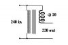
could someone give me some idea what idle current to expect from a
transformer on my 240 volt house mains ?

I am thinking of a 500watt or maybe a bit bigger if the idle current is
fairly low, maybe a 1000watt if the idle current is low.

Is it possible to reduce the idle current by matching a capacitor to
the transformer ?

Cheers, John :)
 
The idle current strongly depend from iron core quality and assembly.
(one old trafo with M-core 80VA suck 75mA, the modern 75VA trafo with welded E-I core sucks 98mA!)
An 500VA transformer can suck about 500...800mA.
Yes, You can compensated with condenser the reactive part of current
(when measured the current with multimeter, and apply a paralel cap.
with primary winding, the current decreased,because it compensate
the cos-fi.) But this method not better for You, because the motor-type
kilowatt-hour-meter no measure the reactive part.(with compensation
Your costs higher...)
 
Hi Sebi,

Thanks for the info.
I am surprised that you say that a 500 W transformer can
draw up to half an ampere with no load!

I would be using the older type construction with removable
laminations, and i would be packing them tightly with minimum
air gaps, as i understand these reduce the overall efficiency.

But i did not know that the lamination shapes had any effect.

Do you mean that the 'E' & 'I' type would be more efficient
than the 'T' & 'U' type, i have seen closed types that have
the middle section made like a tongue, and you sort of slot
them over and in, when in there are no joins around the edges.

What about toroidal types, are they much better ?

I can't see me wanting to leave a half an ampere running
continually on my house mains.
I did not realise the idle current would be that much.

As for the capacitor correction,
i actually thought that the inclusion of a cap
would improve the current/voltage angle, and reduce the peak
current demand.
You say the KWH meter does not cover this ?

I suppose their costing is on current only?
Maybe their profits are more if they charge for 'out of phase'
or unused current.

Regards John :)
 
Hi,

I'm also trying to find out about 'Ferroxcubes' without much
success. Do you think they would have a lower idle current ?

I'm thinking of feeding some of my lighting circuit with a
slightly lower voltage because i am getting too many lamps
burn out, the voltage is around 240, i intend to drop it to
about 220. The lamps are not quite as bright at that, but not
noticeably dimmer. I am hoping they will last longer.

I was thinking of a transformer with '240 in, 220 out' but i
am now wondering if i could just use a 20v winding, 240 in
20 out, and just put the 20 volts in series with the supply.

That would mean instead of looking for 500watts i would be
looking for about 60 or so. And the idle current would be
less. ... if i can do it like that??

My brain hurts now.

Cheers, John :)
 
Hi,

I'm not sure about the way the wattage works out with the
'autotransformer' type of arrangement, if thats what it is...

Any suggestions?

John :)
 

Attachments

  • Transformer.jpg
    Transformer.jpg
    25.1 KB · Views: 957
Hi,

This will probably be the arrangement that i try to do,
i am guessing that the transformer would only handle
the power difference from the 240 to the 220.

That would mean that the transformer could possibly be
handling about 40 per cent of the power transferred,
thats just a guess. (maybe less ?)

So how could i estimate the idle current ?

John
 

Attachments

  • Auto-trans.jpg
    Auto-trans.jpg
    11.7 KB · Views: 907
Hi, John

sorry for the late answer, i'm surprised if my computer clock and date go to 2002 jan. i can't see the new posts.
And now understand completely what You need....
You need only 240V minus 20V with 500VA capability.
The current only about 2.2A.
20V 2.2A only about 50VA, so You need a 240/20 (24)V 50VA regular
transformer, the secondary serial in load with reverse phase.
 

Attachments

  • Auto-trans_155.jpg
    Auto-trans_155.jpg
    4.3 KB · Views: 921
Thanks Sebi,

So that approach is a workable set-up then ?
From what you say, a fifty watt transformer should cover it.
I reckon thats about 50mA idle current, roughly.

Would it be difficult to make some sort of sensor, to switch
it off when no lights are on?
I have been thinking about this for a while, if it could be
turned off when the lights are off, it would save a bit on
the idle current.

Still 50mA may not be too bad, i will try to work it out for
the price of a quarter (three month period) at ten pence per
unit (Kilo-Watt Hour), maths not my strong point !!

Cheers, John :)


did you say you set back the date on your PC, and this
stopped you seeing the new posts ? Are you on 98se ?
I will have to watch out for that, i often alter the date
to use CDs that have date-expired.
 
Yes, if You switched of the primary of trafo, the secondary works
as a piece of wire so the output is 240V. For current sensing - i think -
the simply method a current-relais. Do it yourself from any small relais
with new winding (coil). (wire diameter about 0.5mm, and enough turns for minimum load sensing...)

P.S. I use XP with a defected motherboard. It have only a small failure:
no sense the backup battery, and without mains power forget the setup.
 
Hi Sebi,

You're using 'XP' ... ?
**broken link removed**

The thing with current sensing is that the initial supply would be
at the full voltage. The lamps usually blow at switch-on anyway.

I was thinking maybe the current sensing could be on the lighting
circuit at a very low voltage, until lighting is switched on.
Then the transformer could be switched in, without the lamps ever
getting the higher voltage, but i haven't figured a way yet !!

I am still looking at this, and i haven't figured the cost yet
either.

10p/KW Hr for 3 months at @ 50 mA,
thats if i leave it on.

John :)
 
Maybe simplyer if You apply NTC serial with lamp(s). PC-PSU also contain it for initial current reducing.
 
well, i have fixed up a small transformer, 20 watts, to the lamp
in my kitchen. its giving me a 15 volt drop to about 220 volts.

The lamp is not noticeably dimmer, the transformer uses about
35mA idle current, but i have it go on with the light switch,
so its not on all the time.

If this lamp lasts an appreciably longer time, i shall extend the
arrangement to more of my lighting circuits.

And i should try to work out how much 35mA would cost for 3 months
at about 10p per kW/H.

I'll see how it goes, Cheers, John :)
 
Thanks Ron,

I havent got it down to an equation yet!
By the way, ... could you tell me anything about NTC ?
(from three posts back)
I'm having a hard time pinning it down on google.

John :)
 
follow-up

Hi,

I've been replacing most of the lamps in my house with
the 'low-energy' types.

They work fine and i've only had one fail in a few years.

John :)
 
john1 said:
Thanks Ron,

I havent got it down to an equation yet!
By the way, ... could you tell me anything about NTC ?
(from three posts back)
I'm having a hard time pinning it down on google.

John :)

NTC = negative temperature coeficient.

The device DECREASES its resistance as it gets hotter - resistors do the opposite. It looks like a small disk with two leads, a bit like a fat ceramic capacitor.

Klaus
 
john1 said:
As for the capacitor correction,
i actually thought that the inclusion of a cap
would improve the current/voltage angle, and reduce the peak
current demand. You say the KWH meter does not cover this ?
I suppose their costing is on current only?
Maybe their profits are more if they charge for 'out of phase'
or unused current.

As far as I am aware, the vast majority of domestic installations are charged per kWh, not Ah (I don't know about your location, but certainly in Australia this is the case). Normal electricity meters DO take account of phase angle, and VAr's are not charged, only 'real' watts.

Thus, if you have an idle current of 500mA, at a phase angle of, say, 80 degrees, you are only charged for 86mA (ie, cos 80 * 0.5A).
 
Hi,

Thank you all for your help and advice,
i've decided to go with the 'long-life' lamps,
instead of reducing the lighting supply voltage by a percentage.

I still feel that a small voltage reduction would give a much
longer life to filament lamps, but using these new lamps is so
much easier.

In case anyone is interested, i have found that a reduction in
voltage which can barely be noticed in loss of brightness will
give a significant extension to the life of the lamp.

Best regards, John :)
 
Status
Not open for further replies.

Latest threads

New Articles From Microcontroller Tips

Back
Top