Electro Tech is an online community (with over 170,000 members) who enjoy talking about and building electronic circuits, projects and gadgets. To participate you need to register. Registration is free. Click here to register now.
Welcome to our site! Electro Tech is an online community (with over 170,000 members) who enjoy talking about and building electronic circuits, projects and gadgets. To participate you need to register. Registration is free. Click here to register now.
I was just wondering, if the diode were ideal, could it be used as a demodulating device?
By ideal diode I mean that the diode would behave as a conductor in forward bias stage.
What do you think ?
For modulation/demodulation, what you need to avoid is time invariant linearity. That means that any non-linear (i.e. plate detector) or time-varying linear (dual gate MOSFET, singly balanced differential product detector, pentagrid converter, OTA) or piece-wise linear (switching detector) will demodulate.
An ideal diode would give an ideal piece-wise linear transfer characteristic.
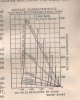
The intersection of the RMS input line and the resistance load line gives the output voltage and current. For example, 20 VRMS input and 50,000 ohms intersect at 22.5 volts output and 450 uA current. This particular dual diode has two plates and one cathode, which is typical of most tube (valve) rectifiers.
As in my first post, I was just wonderinf if an ideal diode shall demodulate AM signals? And the Ideal Diode chacteristics as I belive, is posted above.
And about the valve picture - I guess that X-axis is the DC voltage the Y-axis is the Current (DC ?) and the characteristics also shows AC characteristics (the sloping lines)
But the title says that it is about a half wave rectified output. So everything should be RMS and the input should be AC. In this case what is the DC voltage developed by the diode(X-Axis)?
A diode, ideal or otherwise, passes current in only one direction, so if AC is applied, the output is DC. The current can be collected in a capacitor which will provide a peak voltage at no load. In order to demodulate an AM signal, the capacitor must have a load that will discharge the cap as fast as the highest frequency that is to be recovered.
I was thinking that there is no voltage change when the diode is forward biased there might be no signal....
I just realised that the graph(The one I posted.) showed the voltage drop across the diode and the signal would be developed as the voltage drop across the load resistor.
This site uses cookies to help personalise content, tailor your experience and to keep you logged in if you register.
By continuing to use this site, you are consenting to our use of cookies.