Continue to Site

Welcome to our site!

Electro Tech is an online community (with over 170,000 members) who enjoy talking about and building electronic circuits, projects and gadgets. To participate you need to register. Registration is free. Click here to register now.

  • Welcome to our site! Electro Tech is an online community (with over 170,000 members) who enjoy talking about and building electronic circuits, projects and gadgets. To participate you need to register. Registration is free. Click here to register now.

Diode Anemometer Circuit

For The Popcorn

Well-Known Member
Most Helpful Member
Years ago I saw a simple circuit using a pair of diodes to make an thermal anemometer. Now that I have a need for one, my Google search powers are wearing thin.

I'm working on improving a laser cutter filter system, and one of the things I'm like to do is measure air velocity in the duct to detect filter condition. A thermal anemometer seems like a good way to go. It will feed into a PIC18F-series micro to some kind of indicator.

Has anybody got a simple circuit example?


My alternative is a differential pressure sensor across the filter. I can't say I see any great difference between the two approaches as far as telling when a filter is clogged.
 
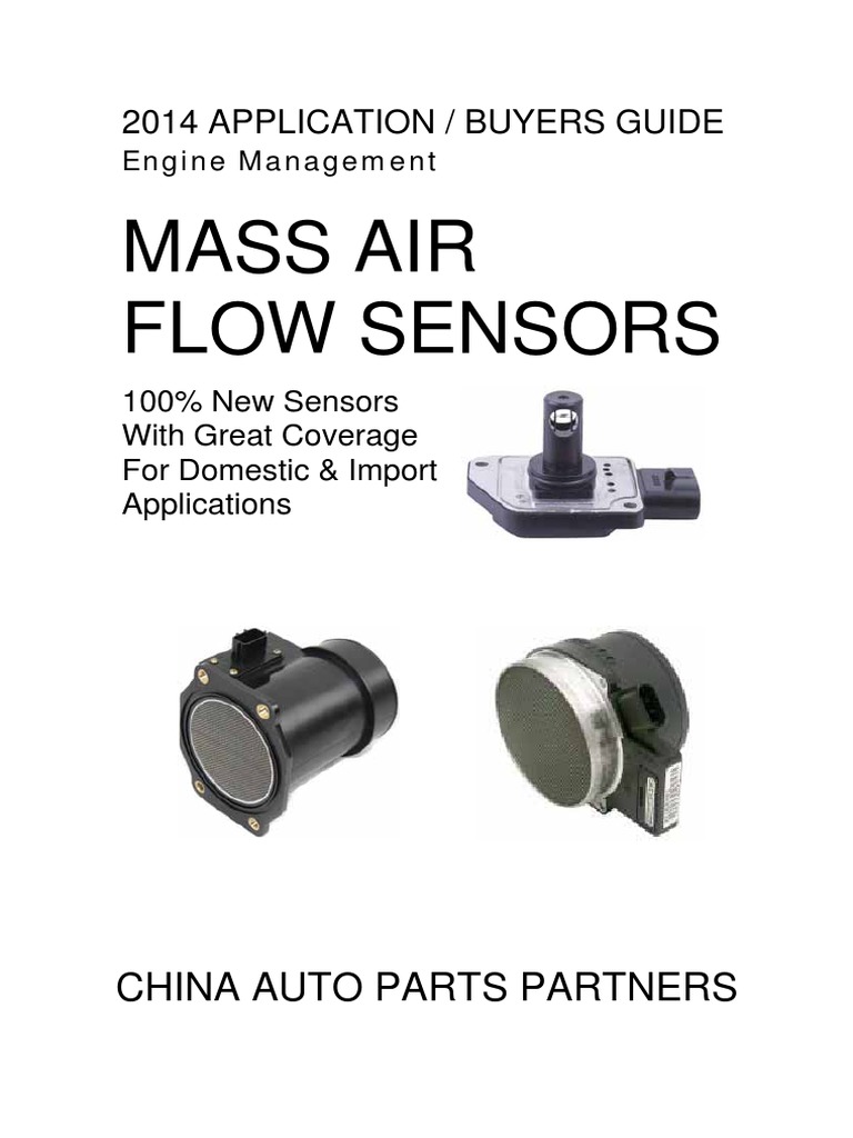
You could use a car "Mass airflow sensor" - they already have the signal conditioning built in!

If you look on ebay, the cheapest types start at around £5
 
You can also suspend a 4 to 6" paper strip from one end and check how it blows up your stack. Then use a little IR emitter detector pair or reflective distance sensor place just above the strip. If the strip is blowing up the stick, the sensor will detect the reflection off the paper. If the paper is sagging, it will not be seen by the detector.


Easier to implement but you'll have to worry about keeping the LED and the ir sensor clean but the paper (or Mylar) strip should make a shadow to keep particulates away.
 
Last edited:
The first link is the way I decided to go, changing the INA 221 instrumentation amp to an MCP 6N16 instrumentation amp for a third the price. The BOM cost, excluding circuit board, is roughly $4.
 
Years ago I saw a simple circuit using a pair of diodes to make an thermal anemometer. Now that I have a need for one, my Google search powers are wearing thin.

I'm working on improving a laser cutter filter system, and one of the things I'm like to do is measure air velocity in the duct to detect filter condition. A thermal anemometer seems like a good way to go. It will feed into a PIC18F-series micro to some kind of indicator.

Has anybody got a simple circuit example?


My alternative is a differential pressure sensor across the filter. I can't say I see any great difference between the two approaches as far as telling when a filter is clogged Outsunny 01-0006-002 download instruction manual pdf.
I am designing a circuit for a fountain. I want the pump to stop if there is no water, if there is a risk of the water freezing or if the wind is strong enough that the water will blow far enough to miss being collected and so empty the reservoir. The first two are fairly easy to arrange but how do I measure the wind speed? An anemometer would be overkill.

I had an idea for using two thermistors across the 5V supply with values low enough that the power dissipation would warm them slightly. Then, with one of them inside the box and one of them exposed to the wind the voltage would be a rough measure of the wind speed as the wind cools the exposed one.

Is this viable? Are suitable components available?
Is there a better way?
 
You can use an ultrasonic sensor aimed at the water in the basin.
This one has an .i2C control and an onboard temp sensor. Although it cannot measure wind speed, you can infer that it is windy if you loose some amount of water level in a given time.

 
I had an idea for using two thermistors across the 5V supply with values low enough that the power dissipation would warm them slightly.


That's nearly exactly was was described in this link from above. I modified it to use a cheaper.... er, less expensive..... instrumentation amp at about a third the cost of the specified one. I believe this to be a good adaptation of the original circuit but I haven't built it yet. The output will range from 0 to almost 5 volts, and provides a non-linear output proportional to wind speed.

No guarantees at this point.

Notes_231014_232342_b76.jpg
 
I should note the top end of R6 from the zero pot should be connected on the sensor side of R8. Sorry if this caused anybody grief.
 
I've considered those, but unlike electronic components, it's virtually impossible to find datasheets on things automotive. They must exist, but aren't accessible for the guy trying to buy ONE.

I'm afraid they wouldn't have the dynamic range to measure flow in a large duct.
 
I've considered those, but unlike electronic components, it's virtually impossible to find datasheets on things automotive. They must exist, but aren't accessible for the guy trying to buy ONE.

I'm afraid they wouldn't have the dynamic range to measure flow in a large duct.
It's quite easy to find the datasheets. You open Google, read the manufacturer's name and model number from the MAF, type it into the search bar on Google, press enter (or click "search").

I've owned a lot of Nissan products and they are typically using Bosch MAFs.

Here's the last one I looked at - still sitting on an unfinished project. Bosch has the same meter body in analog output (off highway) and various digital protocols. You can also get a wide range of kg/hr ranges (An odd unit of measure but it makes for decent integer-based values for quick calculations with 30mSec time-constant for good resolution and update speed). Good luck.
 
It's quite easy to find the datasheets. You open Google, read the manufacturer's name and model number from the MAF, type it into the search bar on Google, press enter (or click "search").

Yep. Easy peasy.

SmartSelect_20231119_122719_Edge.jpg
 
It would seem that you've proven my point since you apparently couldn't find a single non-paywalled version or a datasheet for any of the common types from US manufacturers..

I don't think a MAF sensor is effective at the relatively low flow rates I need to measure. If anybody can find an actual datasheet documenting flow rate vs output, I'd love to see it.
Sorry, I was searching for the specific model you posted and, as suspected, you are too cheap or the request isn't important enough to pay for it. Next time, follow instructions - you didn't include a manufacturers name in the search as I told you to do - you also put a leading "#" on the part number which confuses many search engines. I don't know how some people get through their day and collect a salary.
 
Last edited:

Latest threads

New Articles From Microcontroller Tips

Back
Top