'163 is a synchronous binary up-counter with synch. pre-load.
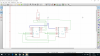
Step 1. Figure out how to connect two cascaded '163s so that they would naturally count 0 to 255. See
the data sheet
Step 2. Wire the two sets of ABCD inputs to the pattern 33 (00100001)
Step 2. Decode state 77 (01001101). Looks like it will take a four input gate to do that...
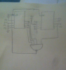
Step 3. Use the gate output to control the Load input(s) so that the counter naturally transitions from 77 to 33 on the 45th clock cycle.
Note that it will take extra logic to preset the counter on power up. If you dont, the counter could power-up in any state between 0 and 255, meaning it will take a random number of clock cycles (up to 255-45) before it gets into the 33-77 sequence.

") 77 output connect to load okay. where is connecting 33 ? and is rco empty ?
77 output connect to load okay. where is connecting 33 ? and is rco empty ?