Continue to Site

Welcome to our site!

Electro Tech is an online community (with over 170,000 members) who enjoy talking about and building electronic circuits, projects and gadgets. To participate you need to register. Registration is free. Click here to register now.

  • Welcome to our site! Electro Tech is an online community (with over 170,000 members) who enjoy talking about and building electronic circuits, projects and gadgets. To participate you need to register. Registration is free. Click here to register now.

I request diagram of MXR EVH Phaser 90 (smd components)

Status
Not open for further replies.
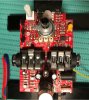
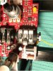
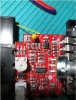
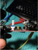
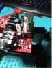
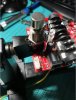
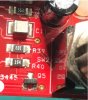
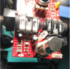
Hello everyone, and I would appreciate if you could help me with a diagram that I am looking for from the MXR Phaser 90 EVH version limited edition, the pedal had a burnt diode, I replaced it and now it turns on but in bypass mode it sounds normal when I turn on the pedal it sounds with Very low volume and does not effect phaser.

in advance thanks to those who can help me
 
This is the Phase 90 schematic, I have no idea on the "limited edition" version - I'd expect it to be internally pretty much the same.
Which diode was it that you replaced?


Edit - if it was D1, it's most likely had a generic PSU with the common "positive centre" plug wiring connected to it, which would apply reverse polarity to the entire circuit.
Guitar pedal PSUs are almost unique in using positive outer on the plug, and a wrong PSU polarity is quite a common error, if people only look at the output voltage.

Any or all the ICs may need replacing, in that case.
 
Last edited:
Thank you for your help, unfortunately it is not the same schematic, it uses smd components and it is similar but it is not the same diagram, attached some photos so you can see the pedal

de diode was C1 you can see its not install, i take out just to check the new diode was not bad but its ok, so any other idea?e
 

Attachments

  • IMG_6857.JPG
    IMG_6857.JPG
    196.1 KB · Views: 364
  • IMG_6858.JPG
    IMG_6858.JPG
    215.6 KB · Views: 333
  • IMG_6859.JPG
    IMG_6859.JPG
    191.1 KB · Views: 616
  • IMG_6860.JPG
    IMG_6860.JPG
    144.4 KB · Views: 313
  • IMG_6861.JPG
    IMG_6861.JPG
    161 KB · Views: 278
  • IMG_6862.JPG
    IMG_6862.JPG
    177 KB · Views: 327
Hi,
I can't find a schematic for the surface mount version.
It looks to be exactly the same basic diagram, just using a dual and a quad opamp rather than six separate ones.

If you run it from external power, do either of the ICs get warm? That would be a giveaway of one needing replacement.
I'd probably be tempted to change them both, they are readily available and not expensive.

 
thanks i alredy order, but 1 more question, thise Q5 the one that is right next to the footswitch, is labeled as 2QY or 2Oy I can not read it well but it is one of these two options, could you indicate which one it is since in the case that it is not in good condition I must change it too, but I can't find it on the internet
 

Attachments

  • Sin título.jpg
    Sin título.jpg
    103.6 KB · Views: 321
  • Sin título12.png
    Sin título12.png
    1 MB · Views: 313
Probably MMBT5087, the surface mount version of a 2N5087. It's a low noise PNP amplifier transistor, which fits with the use in the circuit. The ID code is just 2Q, the other markings will be batch code or date code etc.

It has relatively high value resistors around it so it's unlikely to have been damaged by reverse polarity.

 
ok, thanks again for your help, updating what I have done so far, today the 2 ic arrived, replace them and the pedal worked perfect for 1 or 2 minutes, after that the pedal is sounding with a noise or static, which I could see is that in the negative leg of the CR1 diode the nine volts enter, in the negative of the CR2 they enter at the beginning 3v and then the voltage slowly drops to 1.4v, what could be causing that? I know it is difficult without the schematic but I did not get it on the internet, I already wrote to the jimdumlop company but they do not provide any help in this regard.
 
hello, with great joy I must say that I could finally repair the pedal, after changing the 2 ic, the pedal worked correctly for about 2 minutes and then the pedal towards an unpleasant sound, I thought it was something worse, but in the end it turned out to be that the potentiometer had broken one of the legs, I realized and soldered it and now the pedal works perfectly, thanks for your help.
 
Status
Not open for further replies.

Latest threads

New Articles From Microcontroller Tips

Back
Top