Continue to Site

Welcome to our site!

Electro Tech is an online community (with over 170,000 members) who enjoy talking about and building electronic circuits, projects and gadgets. To participate you need to register. Registration is free. Click here to register now.

  • Welcome to our site! Electro Tech is an online community (with over 170,000 members) who enjoy talking about and building electronic circuits, projects and gadgets. To participate you need to register. Registration is free. Click here to register now.

I prototyped my first circuits today

Status
Not open for further replies.

tony ennis

New Member
Spent a fair amount of time figuring out what voltages my power supply runs at, how to use a multimeter, and how the prototype boards work. Pretty basic, lol.

Then I made an LED light up. Oooo! :p

Then I made a 555 light said LED once a second (or so.)

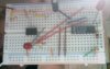
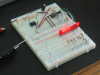
Then I connected the 555 to a 4040 counter and more LEDs.

My protoboard looks like it was wired by a drunk monkey. :D
 
Last edited:
My photography skills nearly equal my electrical engineering skillz.
 

Attachments

  • Photo 4.jpg
    Photo 4.jpg
    49.8 KB · Views: 279
I bought a 'wire kit' and was too prissy to actually bend the nice stright wires, lol. :D

I was unable to use my new strippers to strip bell wire. Perhaps they would work on larger wire...
 
Last edited:
I make nice and tidy circuits on Veroboard (stripboard).
Even the huge and complicated circuits are nice and tidy.
I laugh when I see the mess of wires all over the place on a breadboard circuit (wired by a drunk monkey?).
 
I have several books by Jim Williams, noted analog designer. His prototypes look much more messy than this. Mine tend to look messy too, but they work.
 
The final version, after I raided the scrap bin for LEDs.
 

Attachments

  • counter.png
    counter.png
    546.7 KB · Views: 294
Last edited:
My Veroboard/stripboard circuits look like this. There is only solder joints without any wires on the other side of the circuit board. The wiring is neat and tidy.
 

Attachments

  • Sound Level Indicator 004.jpg
    Sound Level Indicator 004.jpg
    28.4 KB · Views: 348
My Veroboard/stripboard circuits look like this. There is only solder joints without any wires on the other side of the circuit board. The wiring is neat and tidy.
Anytime you build a simple circuit, you break out the soldering iron?
Seems very impractical.
 
Breadboard can be used again and again, stripboard can only be used once.

I prefer breadboard for prototypes, for one-offs I use stripboard, if I want to make neat one-offs or many I design a PCB.
 
Progress / learning = good. Keep it up! Your breadboard looks great. Makes mine look like it was wired by ten crack monkeys at the same time.

Michael
 
A clean circuit board is MUCH easier to De-Bug
I design and make my circuits work perfectly so I don't need to de-bug.
But if I want to change a resistor, capacitor or IC it is easy to (slurp, slurp) solder-suck out one part and solder in a replacement on my Veroboard.

Here is a pic of my almost finished project that was powered for the first time:
 

Attachments

  • Sound Level Indicator 002.jpg
    Sound Level Indicator 002.jpg
    47.1 KB · Views: 197
I design and make my circuits work perfectly so I don't need to de-bug.
But if I want to change a resistor, capacitor or IC it is easy to (slurp, slurp) solder-suck out one part and solder in a replacement on my Veroboard.

Here is a pic of my almost finished project that was powered for the first time:

That's similar to the enclosure I want to use for the "Toggle#1 circuit" I'm going to build. I seen it at radio shack. It seemed to have more slots than the local electronics stores enclosures.

I have about $70.00 in strip Veroboards coming I think I can get 2 circuits per board fitting into one slot hopefully I may be able to get all 12 circuits in one enclosure.

In addition to that the Veroboards at Radio Shack are square pads and the ones sold at the Local Commercial Electronics Company only carry's the round.

It's more difficult to solder bridge 2 points with round than it is for the square the distance between pads are tighter on the square allows you to avoid using wire.

kv:)

Edit: I did have to breadboard the Toggle #1 circuit to test it first though. A lot of guy's on the site don't need to. They develop on the fly like Guru.:rolleyes:
 
Last edited:
Status
Not open for further replies.

Latest threads

New Articles From Microcontroller Tips

Back
Top