Continue to Site

Welcome to our site!

Electro Tech is an online community (with over 170,000 members) who enjoy talking about and building electronic circuits, projects and gadgets. To participate you need to register. Registration is free. Click here to register now.

  • Welcome to our site! Electro Tech is an online community (with over 170,000 members) who enjoy talking about and building electronic circuits, projects and gadgets. To participate you need to register. Registration is free. Click here to register now.

i need some advices on this project

Status
Not open for further replies.

lynx

Member
Hi

since many years i'm trying to build a functional ESR meter...
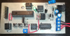
up to now i've found online and built 3 different meters but none of them
was a succesful design, the last one i've build was quite complex and seemed
more serious design (as you can see in the attached photos) but it's not working
as it should.

although there is a display output the capacitance indication remains Cx ---

1. tried to look for broken joints or shorts but i found none.
2. tried to measure for an output test frequency i think it should be something like 100Khz)
but there's no output.

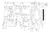
maybe the problem is somewhere around the op-amp but i'm not that expert to figure out
by myself, mostly i want you to indicate some test points to check and what i should expect
on these test points, can you help me? thanks!

original project was descussed in the following website (needs google translator)

**broken link removed**/
 

Attachments

  • ESRmeter1.png
    ESRmeter1.png
    635.5 KB · Views: 160
  • esrmeter2.png
    esrmeter2.png
    691.4 KB · Views: 151
  • ESRmeter3.png
    ESRmeter3.png
    1.1 MB · Views: 146
  • SCHEMATIC.png
    SCHEMATIC.png
    80.6 KB · Views: 143
  • PCB_LAYOUT.png
    PCB_LAYOUT.png
    149.7 KB · Views: 147
Last edited:
Looks like one of the op amps is in backwards, or the socket is back to front.
Do you have anything on pin 12 of the pic, looks like that is the test frequency.
 
Hi

thank you very much for the reply!!

seems i'm not getting anything on pin #12 unless if i am measuring wrong pin
or in wrong way.

(on the ESRmeter3.png photo i'm measuring the 3rd pin from the left .. on the
buttom row of the microcontroller pins)

Which IC looks like it is placed wrong way? because i think all of them are placed right.

Testing different capacitors the ESR indication changes, although the capacitance
measurement it's always Cx ---
 
Last edited:
The 8 pin chip to the right of the preset looks backwards.
Pin 12 is the drive to the output fet, without this you wont get the ac on the test terminals, a scope would show you a square wave most likely, a meter would show you the average dc level, and a logic probe would show a pulse.
If theres no ac on pin 12 then it might be something as simple as the device is not in test mode or something, maybe you need to initiate a test by pressing a button or something.
 
the ESR measurment seems functional though....but i'm not sure if it is accurate

The TL082 black dot which indicates pin #1 matches the square pad on the
pcb which also indicates pin #1, isn't it??

concerning the output on pin #12, i'm using a frequency meter, maybe that's
why i'm not getting any reading?
 
Last edited:
any other member wishes to say an opinion? it can be very helpful
since it looks like i haven't noticed something on my build.
 
guys can you help with that? no ICs are placed wrong
because in that device can't start, the display remains blank.
probably the regulator shuts down.

there's some flactuating voltage on pin #12 but the frequency
meter can't pick anything, probably needs an oscilloscope
which currently i can't find one.

is anybody willing to donate me a Rigol to do
my measurements and than i send it back? :D
 
Last edited:
Status
Not open for further replies.

New Articles From Microcontroller Tips

Back
Top